Transcription of INSTALLATION MANUAL - Trina Solar
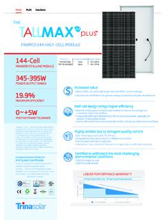
1 Date: April, 2016 DOC: PS-M-0434 A Page - 1 - of 15 INSTALLATION MANUAL IEC & UL version The Honey/Allmax Module TSM-PC05A TSM-PD05 TSM-PE05A The Honey Plus Module TSM-PC05A(II) (II) The Tallmax Module TSM-PC14 TSM-PD14 TSM-PE14A The Honey M Module TSM-DC05A The Honey M Plus Module TSM-DC05A(II) (II) (II) TSM-DD05A(II) (II) (II) The Tallmax M Plus Module TSM-DD14A(II) The Trinasmart Module (II) (II) The Trinaswitch Module (II) (II) The Trinapeak Module The Splitmax Modue (II) The Quadmax Module The Airmax Module TSM-PC05B The Spacemax Module (II) Date: April, 2016 DOC: PS-M-0434 A Page - 2 - of 15 Table of Content 1. DISCLAIMER OF LIABILITY.
2 - 3 - 2. SAFETY PRECAUTIONS .. - 3 - 3. UNPACKING AND STORAGE .. - 5 - PRODUCT IDENTIFICATION .. - 5 - 4. ENVIRONMENTAL CONSIDERATIONS .. - 5 - CLIMATE CONDITIONS .. - 5 - 5. SITE SELECTION .. - 6 - 6. MOUNTING INSTRUCTIONS .. - 6 - MOUNTING METHODS .. - 6 - A. Mounting with Bolts .. - 6 - B. Mounting with Clamps .. - 7 - GROUNDING .. - 10 - MODULE WIRING .. - 12 - 7. ELECTRICAL CONFIGURATION .. - 13 - FUSING .. - 13 - INVERTER SELETION AND COMPATIBILITY .. - 13 - 8. MAINTENANCE AND CARE .. - 14 - 9. WARNING .. - 15 - Date: April, 2016 DOC: PS-M-0434 A Page - 3 - of 15 1. DISCLAIMER OF LIABILITY The INSTALLATION , handling and use of Trina Solar crystalline modules are beyond company control. Trina Solar does not assume any responsibility for loss, damage, injury or expense resulting from the improper INSTALLATION , handling, use or maintenance.
3 Trina Solar assumes no responsibility for any infringement of patents or other rights of third parties that may result from use of the module. No license is granted by implication or under any patent or patent rights. Specifications included in this MANUAL are subject to change without prior notice. 2. SAFETY PRECAUTIONS Potentially lethal DC voltages can be generated whenever PV Modules are exposed to a light source, therefore, avoid contact with electrically active parts and be sure to isolate live circuits before attempting to make or break any connections. Only authorized and trained personnel should have access or perform work on the modules or Solar system, always wearing rubber gloves and boots with maximum working voltage not lower than 1000V DC (For TSM-PE05A.**, PE14A.**, not lower than 1500V DC). When working on electrical connections, remove all metallic jewelry, use properly insulated tools and wear appropriate personal protective equipment to reduce the risk of electric shock.
4 Do NOT stand or step on, damage or scratch the front or backside surfaces of the module. Broken modules cannot be repaired and contact with any module surface or frame can lead to electrical shock. Do NOT use a module with broken glass or torn substrate. Do NOT disassemble the modules or remove any part of the module. Protect the electrical plug contacts against corrosion and soiling. Make sure that all connectors are corrosion free and clean before making the connection. Do NOT install or handle modules when they are wet or during periods of high wind. Ensure that all connections are securely made with no gap between the contacts. Any gap can result in electrical arcing that can cause a fire hazard and/or an electric shock. Make sure that the polarity of each module or a string is not reversed considering the rest of the modules or strings. Do NOT artificially concentrate sunlight on these Solar modules.
5 Trina Solar modules are certified for operating in Application Class A installations at voltages below 1000V DC (For TSM-PE05A.**, PE14A.**, below 1500V DC). This maximum voltage should not be exceeded at any time and, as the voltage of the module increases, above data sheet values, at operating temperatures below 25 C, then these need to be taken into account when designing a PV system. Maximum system voltage must not exceed 1000V DC when UL 1000V products (TSM-**D*. **) are used. Maximum system voltage must not exceed 1500V DC when UL 1500V products (TSM-**E*. **) are used. Do NOT use water to extinguish fires of an electrical origin. Do NOT walk on the modules. Do NOT disconnect the modules under load to avoid arcs and electrical shocks. If needed cover the module surface with an opaque cover. For modules under IEC investigation, under normal conditions, a Solar photovoltaic module is likely to experience conditions that produce more current and/or voltage than reported at standard test conditions.
6 Accordingly, the values of Isc and Voc marked on this module should be multiplied by a factor of when determining component voltage ratings , conductor current ratings , fuse sizes and size of controls connected to the PV output. For modules under UL investigation, most of the time, the Solar module is likely to produce more power, or current , than that rated at standard test conditions. Accordingly, the value of ISC marked on this module should be multiplied by a factor of when determining the conductor current ratings , fuse sizes and size of controls connected to the PV output. Refer to Section of the National Electric Code to check when an additional multiplying factor of may be applicable. INSTALLATION in Canada shall be in accordance with CSA , Safety Standard for Electrical Installations, and Canadian Electrical Code Part System Fire Class Rating of the module or panel in a mounting system in combination with a roof covering complete with requirements to achieve the specified System Fire Class Rating for a non-BIPV module or panel.
7 Any module or panel mounting system has limitations on specific inclination required to maintain a specific System Fire Class Rating. Where common grounding hardware (nuts, bolts, star washers, spilt-ring lock washers, flat washers and the like) is used to attach a listed grounding/bonding device, the attachment must be made in conformance with the grounding device manufacturer's instructions. Date: April, 2016 DOC: PS-M-0434 A Page - 4 - of 15 Common hardware items such as nuts, bolts, star washers, lock washers and the like have not been evaluated for electrical conductivity or for use as grounding devices and should be used only for maintaining mechanical connections and holding electrical grounding devices in the proper position for electrical conductivity. Such devices, where supplied with the module and evaluated through the requirements in UL1703, may be used for grounding connections in accordance with the instructions provided with the module.
8 Rated electrical characteristics are within 10 percent of measured values at Standard Test Conditions of 1000 W/m , 25 C cell temperature and AM Solar spectral irradiance. The fire rating of a Trina Solar PV module is valid only when mounted in the manner specified in the mechanical mounting instructions of this INSTALLATION MANUAL . The module is considered to be in compliance with UL1703 only when the module is mounted in the manner specified by the mounting instructions below. A module with exposed conductive parts is considered to be in compliance with UL1703 only when it is electrically grounded in accordance with the instructions presented below and the requirements of the National Electrical Code for UL listed products only. Any module without a frame (laminate) shall not be considered in compliance with the requirements of UL1703 unless the module is mounted with hardware that has been tested and evaluated with the module under this standard or via a field inspection certifying that the installed module complies with the requirements of UL1703.
9 The Type 1 and/or Type 2 modules with the specified constructions in the table below, when installed with a UL listed mounting system that has been rated as a Class A System, is suitable to maintain the System Class A Fire Rating. Module model Specific construction Marking TSM-xxxPD05 Please check the related UL description files when checking the fire protection rank of the BOM concerned Module Fire Performance: Type 1/ Type 2 TSM-xxxPE05A Please check the related UL description files when checking the fire protection rank of the BOM concerned Module Fire Performance: Type 1/ Type 2 TSM-xxxDD05A(II) (II) (II) Please check the related UL description files when checking the fire protection rank of the BOM concerned Module Fire Performance: Type 1/ Type 2 Please check the related UL description files when checking the fire protection rank of the BOM concerned Module Fire Performance: Type 1/ Type 2 All series in this description All construction in this description Fire resistance rating.
10 Class C (This rating will be invalid after 2016-10-25) The Type 1 and/or Type 2 modules with the specified constructions in the table below, when installed with a UL listed mounting system that has been rated as a Class A System, is suitable to maintain the System Class A Fire Rating. Module model Specific construction Marking TSM-xxxPD14 Please check the related UL description files when checking the fire protection rank of the BOM concerned Module Fire Performance: Type 1/ Type 2 TSM-xxxPE14A Please check the related UL description files when checking the fire protection rank of the BOM concerned Module Fire Performance: Type 1/ Type 2 TSM-xxxDD14A(II) Please check the related UL description files when checking the fire protection rank of the BOM concerned Module Fire Performance: Type 1/ Type 2 All series in this description All construction in this description Fire resistance rating: Class C (This rating will be invalid after 2016-10-25) For cUL listed products only: Fire class rating: C The fire rating of the module is valid only when mounted in the manner specified in the mechanical mounting instructions.