Transcription of Installation of Intrinsically Safe and Nonincendive Systems
1 78 IAEI technology rapidly advancing, newdevel-opments in sensing and process con-trol have increased the number of prod-ucts using Intrinsically safe or Nonincendive circuits astheir protection technique for hazardous (classified)locations as defined in Articles 500 through 505 of the2002 National Electrical Code ANSI/NFPA 70 (NEC) lower Installation and maintenance costs, theseprotection techniques have found increased favor inapplications traditionally requiring explosionproofdevices. Though these concepts have been in use inindustry for many years, some confusion still existsin regards to the Installation of these devices. Fol-lowing the proper Installation requirements is im-portant to the overall safety of Intrinsically safe andnonincendive Safy Safy Safy Safy safe Cire Cire Cire Cire Circuits andcuits andcuits andcuits andcuits andNNNNN onincendivonincendivonincendivonincendiv onincendive Cire Cire Cire Cire CircuitscuitscuitscuitscuitsIntrinsicall y safe circuits and Nonincendive circuits usethe same basic concept to minimize the risk of ignitionof hazardous atmospheres.
2 Both rely on energy limita-tion with some important circuits are permitted in Division2 and Zone 2 classified locations only. Intrinsicallysafe circuits, however, are suitable for use in Divi-sion 1 and 2, and Zone 0, 1 and 2 classified loca-tions. The major difference between the two typesof equipment is that Nonincendive circuits are evalu-ated for ignition capability under normal operatingconditions, while Intrinsically safe circuits are evalu-ated under fault conditions. During an evaluationof an Intrinsically safe circuit, it is allowed to intro-duce up to two independent faults per the require-ments in the applicable product standard in an at-tempt to increase the energy available in the cir-cuit. Under these conditions, the circuit must stillbe incapable of causing ignition of the specified gaseither by introduction of a spark (shorting of twopoints in the circuit) or by thermal effects of indi-vidual components within the determining the inability of a circuit to causeInsInsInsInsInstttttallation ofallation ofallation ofallation ofallation ofIntrIntrIntrIntrIntrinsicallinsicallin sicallinsicallinsically Safy Safy Safy Safy safe ande ande ande ande andNNNNN onincendivonincendivonincendivonincendiv onincendive Sye Sye Sye Sye Syssssstttttemsemsemsemsemsbbbbby Benjamin Py Benjamin Py Benjamin Py Benjamin Py Benjamin P.
3 Sc. Sc. Sc. Sc. Schaefhaefhaefhaefhaefer and Daer and Daer and Daer and Daer and David Pvid Pvid Pvid Pvid P. Malohn. Malohn. Malohn. Malohn. 200279 Installation OF Intrinsically safe AND Nonincendive Systems ignition of a flammable gas or vapor, it is necessaryto consider not only the voltage and current avail-able, but also the capacitance and inductance in thecircuit. Since most circuits contain energy storagecomponents such as capacitors and inductors, theenergy stored by these components must be consid-ered when determining the energy available in thecircuit. The addition of capacitance or inductance toa circuit that is otherwise incapable of causing igni-tion may cause the circuit to become ignition is especially critical when considering fixedequipment interconnected by cables. These cablestypically have known values of capacitance and in-ductance which must be considered in the final sys-tem Installation .
4 Before considering how the capaci-tance and inductance can be accounted for in a sys-tem, it is helpful to have a brief understanding ofthe equipment. The following definitions, taken fromNEC and , are provided for types of equip-ment related to fixed installations of Intrinsically safeand Nonincendive Apparatus. Apparatus in which the cir-cuits are not necessarily Intrinsically safe themselves,but that affect the energy in the Intrinsically safe cir-cuits and are relied on to maintain intrinsic safety. Thistype of equipment contains components that are de-signed to limit the voltage and current available to in-trinsically safe equipment to which it is connected. As-sociated apparatus is generally intended to be installedin unclassified locations, though it can be installed inclassified locations if another protection technique,such as an explosionproof enclosure, is safe Apparatus.
5 Apparatus in whichall the circuits are Intrinsically safe . Associated Nonincendive Field Wiring Appara-tus. Apparatus in which the circuits are not necessar-ily Nonincendive themselves but that affect the energyin Nonincendive field wiring circuits and are relied uponto maintain Nonincendive energy levels. Nonincendive Field Wiring Apparatus. Apparatusintended to be connected to Nonincendive field wiring. Control Drawing. A drawing or other documentprovided by the manufacturer of the Intrinsically safeor associated apparatus, or of the Nonincendive fieldwiring apparatus or associated Nonincendive field wir-ing apparatus, that details the allowed interconnectionsbetween the Intrinsically safe and associated appara-tus or between the Nonincendive field wiring appara-tus or associated Nonincendive field wiring apparatus. Nonincendive field wiring Systems and Intrinsically safesystems shall be wired in accordance with the controldrawing, as required by (B)(3), (B)(3), and (C)(1)(g).
6 The control drawing iden-tification is required to be marked on the referring to Intrinsically safe apparatus andnonincendive field wiring apparatus in the body of thistext, the term field device is used to indicate both,unless specifically indicated otherwise. Similarly, asso-ciated apparatus is used for both associated appara-tus providing Intrinsically safe outputs and for associ-ated Nonincendive field wiring of ApparCombination of ApparCombination of ApparCombination of ApparCombination of ApparatusatusatusatusatusAssociated apparatus and Intrinsically safe apparatusmay be combined to form Intrinsically safe in the same way, associated Nonincendive fieldwiring apparatus and Nonincendive field wiring appa-ratus may also be combined to form a system. Thesecombinations of apparatus are required to be listedtogether as a complete system or the associated appa-ratus and the field device arelisted separately and then mustsatisfy additional Safy Safy Safy Safy Safeeeeeand Nand Nand Nand Nand Nonincendivonincendivonincendivonincendi vonincendiveeeeeSySySySySyssssstttttemse msemsemsemsApparatus listed as a systemare easier to install since allaspects of the Installation aredefined on the control draw-ing provided with the equip-ment.
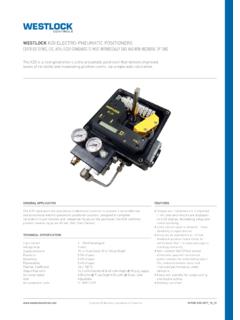
7 Figure 1 is a simplifiedexample of a system controldrawing:On the system control draw-ing, each piece of equipmentthat may be connected in theFigure 1. System control drawing80 IAEI is defined specifically by manufacturer and partnumber. Only the specific equipment included on thecontrol drawing may be connected into the equipment, including portable communicationdevices, may not be used since any additional equip-ment could add either energy storage components oradditional power sources which have not been evalu-ated in combination with the circuits. Additional equip-ment could therefore render the circuit ignition ca-pable. Additional guidance for Intrinsically safe systemscan be found in Wiring Practices for Hazardous (Clas-sified) Locations Instrumentation Part 1: IntrinsicSafety, ANSI/ISA as indicated in NEC should be noted that the control drawing providesinformation regarding the interconnection cable.
8 Insome cases, the drawing will indicate a maximum lengthof cable to be used between the pieces of other cases, a maximum allowable value of capaci-tance and inductance is given and it is necessary tocalculate the allowable length of cable based on itsspecified capacitance and inductance per unit capacitance and inductance of the cable shall ei-ther be taken from the cable manufacturer s datasheetfor the cable, or when not available, then standard val-ues of 60 pF/ft for capacitance and mH/ft for induc-tance are to be used. These values will be found on thecontrol drawing, and are taken from the Standard forSafety, Intrinsically safe Apparatus and AssociatedApparatus for Use in Class I, II, and III, Division 1,Hazardous (Classified) Locations, ANSI/UL ConcepEntity ConcepEntity ConcepEntity ConcepEntity ConceptttttAnother method of interconnecting equipment is com-monly known as the entity concept.
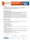
9 This has someunique advantages over Systems . Using this concept,a listed associated apparatus and a listed field device,not necessarily manufactured by the same company,may be connected together without obtaining a list-ing for the specific combination. This allows for muchgreater flexibility in the field when purchasing equip-ment. However, this concept requires special atten-tion be paid to the control drawings, not only for theassociated apparatus, but also for the field device. Thecontrol drawings for each piece of equipment are pro-vided with electrical ratings known as entity param-eters, which represent the limits of the equipment,either with respect to the maximum output character-istics, or the maximum allowable input characteris-tics. These parameters Appared Appared Appared Appared Apparatus Entityatus Entityatus Entityatus Entityatus EntityPPPPP arararararameameameameametttttererererer sssssAssociated apparatus which has been assigned entityparameters, whether providing Intrinsically safe ornonincendive field wiring connections, are assigned theparameters shown below.
10 Where two designators areshown, they are or Uo, this represents the maximum open circuitvoltage that may be present at the specified terminalsunder the most adverse or Io, this represents the maximum short circuitcurrent that may be present at the specified terminalsunder the most adverse or Co, this represents the maximum capacitancethat may be connected to the specified terminals with-out invalidating or Lo, this represents the maximum inductancethat may be connected to the specified terminals with-out invalidating some cases associated appara-tus may also be provided with a Poand/or a Lo/Ro parameter. The Po pa-rameter represents the maximumoutput power from the specified ter-minals. The Lo/Ro parameter is an in-ductance to resistance ratio and in-dicates the maximum inductanceper ohm of resistance that may besafely connected to the specified ter-minals of the associated Safy Safy Safy Safy Safeeeeeand Nand Nand Nand Nand Nonincendivonincendivonincendivonincendi vonincendiveeeeeFFFFF ield Wield Wield Wield Wield WiririririringingingingingApparApparAppa rApparApparatusatusatusatusatusPPPPP arararararameameameameametttttererererer sssssIntrinsically safe and nonincendivefield wiring apparatus are providedINSTALLATION OF Intrinsically safe AND Nonincendive SYSTEMSF igure 2.