Transcription of Installation, Operation, and Maintenance
1 FAXA-SVX01B-ENInstallation, Operation, and MaintenancePackaged Fresh Air UnitFor 100% Outdoor Air ApplicationsModels FADA and FAHA BO and later design sequenceApril 2003 2003 American Standard This ManualLiterature Change HistoryUse this manual for Packaged Fresh Airunits, models FADA and FAHA. This is the B issue of this manual, revised toinclude the total energy wheel option. Itprovides specific installation, Operation, and Maintenance instructions for BO and later design units have modular DDC controlsthat provide operating functions signifi-cantly different than conventional airconditioning units. Refer to the startupand test mode procedures within thismanual. Also, reference the Tranepublication, Packaged Fresh Air UnitProgramming Guide, units with gas heat, also referencethe Reznor Installation Form RGM 401 Installation/Operation/Service of ManualThis manual describes proper Installation, startup, operation, and maintenanceprocedures for the Packaged Fresh Airunit.
2 Carefully review the informationwithin this manual and follow theinstructions to minimize risk of improperoperation and/or component roof curb specifically designed for thePackaged Fresh Air unit is available in14 or 24 height from trane . The curbmust be mounted on a permanent roofstructure before attempting to install theunit. Reference the roof curb installationinstructions in the trane publication, Accessory Roof Curb Kit InstallationManual, FAXA-SVN01B-EN. Dimensionaldata for use with curbs other than trane ,can be found on pages 15-32 of : One copy of this manual shipsinside the control panel of each is important that you perform periodicmaintenance to help ensure trouble freeoperation. Should equipment failureoccur, contact a qualified trane serviceorganization for an experienced HVAC technician to properly diagnose andrepair this : Do not release refrigerant to theatmosphere!
3 If adding or removing refrigerant, theservice technician must comply with allfederal, state, and local and Cautions WARNINGW arnings indicate potential hazardoussituations, which if not avoided, can causedeath or serious injury. CAUTIONC autions indicate a potentially hazardoussituation, which if not avoided, may causeminor or moderate injury. Also, cautionsmay alert against unsafe indicate a situation that maycause equipment or follow below. WARNINGH azardous voltage!Disconnect all electrical powerincluding remote disconnects beforeservicing unit. Follow proper lockout/tagout procedures to ensure powercannot be inadvertently to do so can cause death orserious copper conductors only!Unit terminals are not designed toaccept other type conductors.
4 Failureto use copper conductors may causeequipment HVAC AcronymsFor convenience, a number of acronymsand abbreviations are used throughoutthis manual. These acronyms arealphabetically listed and defined = building automation systemscfm = cubic-feet-per-minuteCKT. = circuitCV = constant volumeCW = clockwiseCCW = counterclockwiseE/A = exhaust airECEM = exhaust/comparative enthalpymoduleF/A = fresh airFAU = fresh air unitGBAS = generic building automationsystemHI = human interfaceI/O = inputs/outputsIOM= installation/operation/maintenancemanual IPC = interprocessor communicationsLCI = LonTalk communication interfaceLH = left-handMCM = multiple compressor moduleMWU = morning warmupNSB = night setbackO/A = outside airpsig = pounds-per-square-inch, gagepressureR/A = return airRH = right-handRPM = revolutions-per-minuteRTM = rooftop moduleS/A = supply airSCM = single circuit moduleSZ = single-zone (unit airflow)
5 TCI = Tracer communications moduleUCM = unit control modulesVAV = variable air volumeVCM = ventilation control moduleVOM = ventilation override moduleZSM = zone sensor moduleSpecial Note on RefrigerationEmissionsWorld environmental scientists haveconcluded that ozone in our upperatmosphere is being reduced due to therelease of CFC fully halogenatedcompounds. trane urges all HVAC service personnel to make every effort toprevent any refrigerant emissions whileinstalling, operating, or servicingequipment. Always conserverefrigerants for continued use and followall warnings and cautions in this reference to related publications: Packaged Fresh Air Unit Programming Guide, FAXA-SVP01B-EN Accessory Roof Curb Installation Manual, FAXA-SVN01B-EN Reznor Installation Form RGM 401, Installation/Operation/Service for units with gasheatInstallation.
6 2 General Considerations ..8 Dimensions/Weights ..15 Mechanical Requirements ..33 Electrical Procedure ..40 Pre-Startup Requirements ..51 Startup ..52 Operation ..54 General Information ..54 Sequence of Operation .. 67 General Information ..67 Maintenance Procedures ..71 Periodic Checklists ..77 Index .. 79 Note: This document is customer propertyand must be retained by the unit s owner foruse by Maintenance 1 Unit modelF = fresh air unitDigit 2 Unit configurationA = air cooledDigit 3 Unit discharge directionD = downflowH = horizontalDigit 4 Development sequenceA = development sequence A Digits 5, 6, 7 Unit size031 = 3100 cfm040 = 4000 cfm051 = 5100 cfm066 = 6600 cfmDigit 8 Unit voltage3 = 230 volt/60 hz/3 ph4 = 460 volt/60 hz/3 ph6 = 208 volt/60 hz/3 phDigit 9 heating system0 = noneA = gas low rise, single bank, 2-stageB = gas low rise, single bank, 2:1modulateC = gas high rise, single bank, 2-stageD = gas high rise, single banks, 2.
7 1modulateE = gas dual bank, 4-stageF = gas dual bank 4:1 modulateG = electric heat, 3-stageH = electric heat, 7-stageK = hydronic interface onlyDigits 10, 11 Design sequence** = factory assignedDigits 12, 13, 14 Heat input000 = none020 = 20 kW026 = 26 kW032 = 32 kW042 = 42 kW056 = 56 kW070 = 70 kW084 = 84 kW100 = 100 kW122 = 122 kW125 = 125 MBh150 = 150 MBh200 = 200 MBh250 = 250 MBh300 = 300 MBh350 = 350 MBh400 = 400 MBh500 = 500 MBh600 = 600 MBh700 = 700 MBh800= 800 MBhDigit 15 Heat exchanger material0 = none1 = 409 stainless steel, 409 stainless Burner2 = 321 stainless steel, 409 stainless burnerDigit 16 Condenser reheat coil0 = none1 = condenser hot gas reheat coilDigit 17 ventilation damper type0 = parallel blade damper1 = TRAQ damper with air flowmeasurementDigit 18 Energy recovery0 = none1 = total energy wheel w/occupancycontrol2 = total energy wheel w/dry bulb controlDigit 19 Return air damper0 = none1 = bottom return/reference enthalpy2 = bottom return/comparative enthalpyDigit 20 Supply fan type1A = 12 - 9 centrifugal fanB = 15 - 11 centrifugal fanC = 18 - 13 centrifugal fanDigits 21, 22.
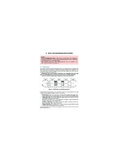
8 23 Supply fan rpm037 = 375040 = 400042 = 425045 = 450047 = 475050 = 500052 = 525055 = 550057 = 575060 = 600062 = 625065 = 650067 = 675070 = 700072 = 725075 = 750077 = 775080 = 800082 = 825085 = 850087 = 875090 = 900092 = 925095 = 950097 = 975100 = 1000102 = 1025105 = 1050 FADA0406GA,00,8,401A01A0,5,70,7A000EF010 ,0,00,0 AAAA1 2 3 4 5,6,7 8 910,11 12,13,1415161718 19 20 21,22,23 24,25 26 27 28 29 30 31 32 33 34,35,36 37,38 39 40 41 42 Packaged Fresh Air unit Model Number DescriptionFollowing is a complete description of the Packaged FAU model number. Each digit in the model number has a corresponding codethat identifies specific unit : The first number in this description indicates thefan wheel diameter (in.)
9 The second numberindicates the fan wheel 24, 25 Supply fan horsepower01 = 102 = 203 = 305 = 507 = = 1015 = 15 Digit 26 Fan motor typeA = standard efficiency ODP fan motorB = high efficiency ODP fan motorDigit 27 Coil protection0 = noneA = corrosion inhibiting coatingDigit 28 Unit cabinet protection0 = standard prepainted steel finishA = corrosion inhibiting coatingDigit 29 Filter type0 = field-provided filter1 = dirty filter switch (DFS) with field-provided filter2 = 2 pleated media filters3 = 2 pleated media filters & DFSD igit 30 System controlA = supply air dehumidificationB = supply air dehimidification with zoneRH referenceE = zone dehumidification107 = 1075110 = 1100112 = 1125115 = 1150117 = 1175120 = 1200122 = 1225125 = 1250127 = 1275130 = 1300132 = 1325135 = 1350137 = 1375140 = 1400142 = 1425145 = 1450147 = 1475150 = 1500152 = 1525155 = 1550157 = 1575160 = 1600162 = 1625165 = 1650167 = 1675170 = 1700172 = 1725175 = 1750177 = 1775180 = 1800182 = 1825185 = 1850187 = 1875190 = 1900192 = 1925195 = 1950197 = 1975200 = 2000202 = 2025205 = 2050207 = 2075210 = 2100 FAXA-SVX01B-EN5 InstallationgeneralinformationF = zone
10 Dehumidification with OA RHreferenceG = supply air temperature control (nodehumidification)J = zone temperature control (nodehumidification)Digit 31 Control interface options0 = noneA = LonTalk communications interface(LCI ) (comm5)B = LCI (comm5) & generic buildingautomation system (GBAS) (0-5 VDC)C = LCI (comm5) & GBAS (0-5 VDC) & ventilation override module (VOM)D = LCI (comm5) & VOME = GBAS (0-5 VDC)F = GBAS (0-5 VDC) & VOMG= VOMD igit 32 Miscellaneous system controloptions0 = none1 = interface for remote human interfaceDigit 33 Exhaust option0 = none1 = exhaust interfaceDigits 34, 35, 36 Exhaust air fan rpm000 = none045 = 450047 = 475050 = 500052 = 525055 = 550057 = 575060 = 600062 = 625065 = 650067 = 675070 = 700072 = 725075 = 750077 = 775080 = 800082 = 825085 = 850087 = 875090 = 900092 = 925095 = 950097 = 975100 = 1000102 = 1025105 = 1050107 = 1075110 = 1100112 = 1125115 = 1150117 = 1175120 = 1200122 = 1225125 = 1250 Digits 37.