Transcription of INSTALLATION, OPERATION AND MAINTENANCE
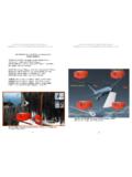
1 installation , OPERATION AND MAINTENANCE Threaded and Wafer Style Flowmeters Table of Contents Wafer Style Flowmeter Figure 1 Page 1. Principle of OPERATION 2 2. installation Planning .. 2 3. installation . 3 Safety Considerations 3 Changing the Dial Orientation .. 3 Changing from Horizontal to Vertical .. 3 Threaded Bodies 3 Wafer style Bodies . 3 4. OPERATION and MAINTENANCE . 4 Preventative MAINTENANCE . 4 Checking Zero . 4 Checking the Pointer Preload .. 4 Coarse Zero Adjustment 4 Fine Zero Adjustment.
2 5 Flow Calibration .. 5 Cleaning of Pressure Ports 6 Adjustment of Reed Switches .. 6 5. Troubleshooting .. 7 Pointer Fluctuation . 7 Zero Shift .. 7 Sluggish Meter Response . 7 6. Correction Factors .. 7 Liquid Service .. 7 Compressed Gas Service . 8 7. Cutaway View .. 8 Figures Figure 1 Wafer style flowmeter .. 1 Figure 2 installation conditions .. 2 Figure 3 O-ring installation . 3 Figure 4 Zero reference point 4 Figure 5 Pointer preload . 4 Figure 6 Cam nut and stop nut.
3 5 Figure 7 Can follower adjustment . 6 Figure 8 Reed switch adjustment . 6 Figure 9 Cutaway view 8 1. Principle of OPERATION installation Planning and Site Selection 2. Page 2 These threaded and wafer style flowmeters measure flow rate by sensing the pressure differential created across the flow nozzle which is machined into the body of the flowmeter. A pair of matched, opposed bellows sense the differential pressure and drive a mechanical linkage to indicate flow rate directly on the dial. (When fitted with a blind transmitter or digital display readout, the bellows and mechanical linkage are replaced with a solid state differential pressure sensor).
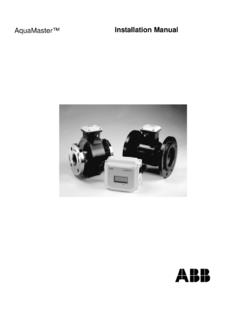
4 Select a site which is convenient for viewing and which provides service access to the front and rear of the flowmeter. Note that the dial can be ordered in any orientation at 90 degree increments and can be easily re-oriented in the field. See Changing the Dial Orientation in the installation section. The site selected should provide at least 10 pipe diameters of straight meter size pipe between the flow meter inlet and any upstream fitting such as elbow, tee or valves. There are no special requirements for the downstream connections to the meter. Note that the flow meters are calibrated based on schedule 40 pipe connections.
5 Tubing and hoses do not have the same ID as pipe and should be transitioned to pipe at least 10 pipe diameter upstream of the flowmeter to achieve rated accuracy. installation Conditions Figure 2 Avoid placing the flow meter where it will be subjected to water hammer and mount the flowmeter rigidly to minimize shock or vibration. Flow meters installed outdoors or exposed to splashing liquids should be ordered with a gasketed case. Protect from freezing liquids. 3. installation Page 3 Safety Considerations Do not exceed the pressure and temperature limits marked on the nameplate of the flow meter.
6 Although each flow meter is pressure tested to 150% of nameplate rating, overpressure may cause injury, leaking or flow meter damage. Temperature ratings are determined by the effects on the mechanical linkage, elastomer seals and electronics (if electronics are fitted). If temperature ratings are exceeded, the flow meter may be damaged or fail. Contact the factory for application assistance for expanded temperature OPERATION . Changing the Dial Orientation Note the flow direction arrows on the body. If necessary, change the dial facing direction by removing the four screws holding the body to the housing.
7 Do not remove the two screws holding the housing to the cell block assembly. Position the housing at any 90 degree position. Replace the four screws taking care not to pinch the o-ring seals. O-Ring installation Figure 3 Changing from Horizontal to Vertical or Vertical to Horizontal Remove the lens by rotating counter-clockwise by hand. Do not remove the pointer. Move the dial forward gently by prying with a small knife at the 12:00 o clock position.
8 Rotate the dial to the desired viewing position and push the dial into position. There are 4 locating indents on the dial edge and housing to position the dial at 90 degree increments. Using a small screwdriver blade to lift the end of the retainer ring up and out of the housing recess, remove the retainer ring and dial crystal. Do not remove the pointer. Remove the two screws holding the dial and rotate the dial to the desired viewing position. Reinstall the screws to hold the dial in position. It may be necessary to shorten the screws to approximately 1/8 (3mm) to avoid contact with gear movement.
9 Rezero the flow meter using the FINE ADJUSTMENT procedure. Threaded Bodies Make up thread joints using a suitable sealant. Be sure threads are clean and free of burrs before making up joint. Wafer Style Bodies Install the flow meter between mating flanges. Take care to center the gaskets so that they do not protrude at all into the pipeline which will cause significant error. O-Rings ABS Housing Aluminum Housing Either Housing 4. OPERATION and MAINTENANCE Page 4 Preventative MAINTENANCE The flow meter does not require routine lubrication or service of any kind. Keep the interior of the flow meter housing clean and free of dust, moisture, oils or corrosive materials.
10 Protect the flow meter from dripping or splashing corrosives or solvents which may attack meter exterior and eventually damage the internal mechanism. Checking Zero Water hammer or pressure surges can displace the bellows and cause the zero to shift. If the pointer does not return to the zero reference point when flow through the meter is zero, or if the pointer does not move away from the zero reference point at 12-15% of full scale flow, then check the zero adjustment as follows: Stop flow. Remove the lens Observe the position taken by the pointer. When properly adjusted, the pointer should point to the zero reference point as shown in Figure 4.