Transcription of Installation, Operation and Maintenance Manual
1 Document #455924. Energy Recovery Ventilators . installation , Operation and Maintenance Manual Please read and save these instructions. Read carefully before attempting to assemble, install, operate or maintain the product described. Protect yourself and others by observing all safety information. Failure to comply with instructions could result in personal injury and/or property damage! Retain instructions for future reference. Models: ERV-251. ERV-361. ERV-521. ERV-581. ERV-522. ERV-582. General Safety Information Only qualified personnel should install this system. 1. Follow all local electrical and safety codes, as well Personnel should have a clear understanding of these as the National Electrical Code (NEC), the National instructions and should be aware of general safety Fire Protection Agency (NFPA), where applicable. precautions. Improper installation can result in electric Follow the Canadian Electrical Code (CEC) in shock, possible injury due to coming in contact with Canada.
2 Moving parts, as well as other potential hazards. 2. All moving parts must be free to rotate without Other considerations may be required if high winds striking or rubbing any stationary objects. or seismic activity are present. If more information is needed, contact a licensed professional engineer 3. Unit must be securely and adequately grounded. before moving forward. 4. Do not spin fan wheel faster than maximum cataloged fan RPM. Adjustments to fan speed DANGER significantly effects motor load. If the fan RPM is Always disconnect power before working on or near changed, the motor current should be checked to this equipment. Lock and tag the disconnect switch make sure it is not exceeding the motor nameplate or breaker to prevent accidental power up. amps. 5. Do not allow the power cable to kink or come in CAUTION. contact with oil, grease, hot surfaces or chemicals.
3 When servicing the unit, the internal components Replace cord immediately if damaged. may be hot enough to cause pain or injury. Allow 6. Verify that the power source is compatible with the time for cooling before servicing. equipment. CAUTION 7. Never open access doors to the unit while it is running. Precaution should be taken in explosive atmospheres.. Energy Recovery Ventilator 1. Receiving Machined parts coated with rust preventive should Upon receiving the product, check to make sure be restored to good condition promptly if signs of all items are accounted for by referencing the bill rust occur. Immediately remove the original rust of lading to ensure all items were received. Inspect preventive coating with petroleum solvent and clean each crate for shipping damage before accepting with lint-free cloths. Polish any remaining rust from delivery. Notify the carrier if any damage is noticed.
4 Surface with crocus cloth or fine emery paper and oil. The carrier will make notification on the delivery Do not destroy the continuity of the surfaces. Wipe receipt acknowledging any damage to the product. clean thoroughly with Tectyl 506 (Ashland Inc.) or All damage should be noted on all the copies of the equivalent. For hard to reach internal surfaces or the bill of lading which is countersigned by the for occasional use, consider using Tectyl 511M Rust delivering carrier. A Carrier Inspection Report should Preventive or WD-40 or the equivalent. be filled out by the carrier upon arrival and the Traffic Department. If damaged upon arrival, file claim with carrier. Any physical damage to the unit after acceptance is not the responsibility of Greenheck Fan Corporation. Unpacking Verify that all required parts and the correct quantity of each item have been received.
5 If any items are missing report shortages to your local representative to arrange for obtaining missing parts. Sometimes it is not possible that all items for the unit be shipped together due to availability of transportation and truck space. Confirmation of shipment(s) must be limited to only items on the bill of lading. Handling Units are to be rigged and moved by the lifting brackets provided or by the skid when a forklift is used. Location of brackets varies by model and size. Handle each piece in such a manner as to keep from scratching or chipping the coating. Damaged finish may reduce ability of the unit to resist corrosion. Storage Units are protected against damage during shipment. If the unit cannot be installed and operated immediately, precautions need to be taken to prevent deterioration of the unit during storage. The user assumes responsibility of the unit and accessories while in storage.
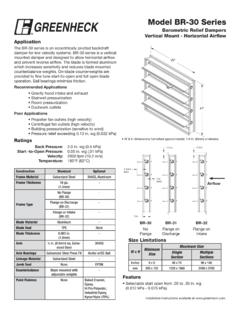
6 The manufacturer will not be responsible for damage during storage. These suggestions are provided solely as a convenience to the user. Inspection and Maintenance during Storage While in storage, inspect units once per month. Keep a record of inspection and Maintenance performed If moisture or dirt accumulations are found on parts, the source should be located and eliminated. At each inspection, rotate all moving components by hand ten to fifteen revolutions to distribute lubricant on motor and bearings. If paint deterioration begins, consideration should be given to touch-up or repainting. Units with special coatings may require special techniques for touch-up or repair. 2 Energy Recovery Ventilator Table of Contents Basic Operation Basic Operation .. 3 The ERV brings in fresh, outdoor air and removes installation stale, exhaust air. Prior to discharging the exhaust Supplemental installation , Operation and air, the energy recovery wheel transfers energy from Maintenance Manuals.
7 3 the exhaust air to the outdoor air at an efficiency installation Concerns.. 3 of 70-80%. Simply put, this unit preconditions the Lifting .. 4 outdoor air to save money on heating and cooling Roof Curb and Rail Mounting costs. Recommended Roof Opening .. 4 Exhaust air Energy Recovery Roof Curb Mounting .. 5 Exhaust air Wheel from building Curb Dimensions and Weights .. 5 discharged Ductwork Connections .. 5 outside Rail Mounting / Layout .. 6. Service Clearances .. 7. Electrical Information General Electrical Information .. 8. Control Center Components .. 9. Electric Heater Application/ Operation .. 9. Unit Accessories.. 9. Outdoor Access Panel Description and Location .. 10-11 air Dimensional Data .. 12-13. Optional Accessories Frost Control Application/ Operation .. 14. Economizer Application/ Operation .. 15. Variable Frequency Drives and Wiring .. 16-17. Typical Wiring Diagram.
8 18. Sensors and Lights .. 19. Preconditioned air Remote Control Panel and Wiring .. 20 sent to space Sensors Mounted by Factory .. 21. Sequence of Operation Start-Up Supplemental installation , Unit .. 22 Operation and Maintenance Optional Accessories .. 23 Manuals Fan .. 24. Energy Recovery Wheel .. 25 Refer to the following installation , Operation and Routine Maintenance Checklist Maintenance Manuals for additional details: General .. 26 Part #460988 ERV-522 and ERV-582 Curbs Fan Belts.. 26. Part #462844 ERV Exhaust Weatherhood Fan Motors .. 26. Fan Wheel and Fasteners .. 27. Fan Bearings .. 27 installation Filters .. 27 The system design and installation should follow Door Seal Maintenance .. 27 accepted industry practice, such as described in the Energy Recovery Wheel Maintenance ASHRAE Handbook. Accessing Energy Recovery Wheel ..27-28. Adequate space should be left around the unit for Removing Wheel Segments.
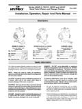
9 28. filter replacement and Maintenance . Sufficient space Cleaning Wheel Segments .. 29. should be provided on the side of the unit for routine Wheel Belt .. 29. service and component removal should that become Wheel Bearing .. 29. necessary. Parts List .. 30. Sequence of Operation .. 31 See Service Clearances and Access Panel Description Troubleshooting Airflow.. 32 sections for more details. Troubleshooting Unit .. 33-34. Maintenance Log .. 35 WARNING. Warranty .. Backcover All factory provided lifting lugs must be used when lifting the unit. Failure to comply with this safety precaution could result in property damage, serious injury or death. Energy Recovery Ventilator 3. Lifting Recommended Roof Opening 1. Before lifting, be sure that all shipping material V. has been removed from unit. 2. To assist in determining rigging requirements, weights are shown below.
10 EXHAUST. 3. Unit must be lifted by all lifting lugs provided on INTAKE. base structure. 4. Rigger to use suitable mating hardware to attach U. to unit lifting lugs. 5. Spreader bar(s) must span the unit to prevent SUPPLY. damage to the cabinet by the lift cables. DISCHARGE. ERV-251, 361, 521 and 581. U. EXHAUST. DISCHARGE. INLET. SUPPLY. V. 6. Always test-lift the unit to check for proper balance and rigging before hoisting to desired ERV-522 and 582. location. 7. Never lift units by weatherhoods. Position the unit roof 8. Never lift units in windy conditions. Unit Size U V. opening such that the 9. Preparation of curb and roof openings should be supply discharge and ERV-251 20. completed prior to lifting unit to the roof. exhaust inlet of the ERV-361 43 26. 10. Check to be sure that gasketing (supplied by unit will line up with ERV-521 58 35. others) has been applied to the curb prior to the corresponding ERV-581 60 30.