Transcription of INSTALLATION/OPERATION MANUAL - Flightcom
1 MODEL 403 Panel-Mount Intercom MODEL 403d Panel-Mount Intercom with Digital Clearance recorder (DCR ) INSTALLATION/OPERATION MANUALCONGRATULATIONS! You have just purchased the best value in STATE OF THE ART cockpit unit is equipped with many new convenient features that will add to your flying READ THIS MANUAL BEFORE USING THE INTERCOM AND CONSULT WITH YOUR A & P MECHANIC OR REPAIR STATION PRIOR TO Intercom Models 403 and 403d are full dual-channel stereo capable units also compatible with monaural headsets. installation of up to six places is possible with the jacks included with both models.
2 Threeof these six places have transmit capability over aircraft radios. Model 403d also includes the Digital ClearanceRecorder (DCR ), which enables instant recall of voice OVERVIEWSPECIFICATIONS Size: 5 L x W x HWeight: : 375 milliwatts into each channel of up to six 150 Ohm headsets. Sound level remains constant regardless of the number or the type of headsets connected. Power Requirements: amps, 12-28 VDCW arranty: two year parts and laborPARTS LIST403 or 403d intercom, labeledAccessory Package:1 25-pin D-sub connector (male)1 25-pin D-sub connector housing1 Large control panel1 Small control panel2 Knobs6 Stereo/mono switches withmounting nuts and washers2 4-40 mounting screws6 Stereo/mono control panels4 6-32 screws1 Allen wrenchManualWarranty CardModel 403d also contains.
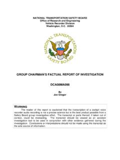
3 1 Wiring harness for DCR, with button, switch, and LED 1 DCR control panel2 LED holders2 Sheet metal mounting screwsFigure 1 - Model 403/403d Typical Connection ConfigurationICSI solateFLIGHTCOM 403 SqVolSTEREOO ptionalDCR Control PanelOptionalPTT Switches for 1-3 placesFLIGHTCOM 403 HEADSET JACKSfor 2-6 PlacesOptionalStereo orMonoICSS quelchVolumeIsolate403 INTERCOMO ptionalSMALL PanelHeadphoneMonoStereo/MonoSwitch Panels (2-6)MicrophoneJackAircraft RadioAudio PanelOptionalPLAYRECORDSTARTD igitalClearanceRecorder Figure 1- Model 403/403d Typical Connection ConfigurationJack package:6 Headphone jacks6 Microphone jacks12 Metal nuts12 Metal washers6 Black fiber shoulder washers6 White nylon or fiber washersSET-UP and INSTALLATIONM ounting the Intercom to the AircraftThe 403 and 403d intercoms can be mounted to the aircraft in either of the following ways.
4 Standard 21/4inch Instrument Hole Mounting Through-panel or Under-panel MountingStandard 21/4inch Instrument Hole MountingTo mount the intercom with standard 21/4inch hole mount:1. Secure the intercom to the large control panel using the two hex nuts and washers located on each potentiometer control shaft (Figure 2 below).NOTE:this is the only time when the potentiometer nuts and washers can be removed and replaced. Do not remove or use them to secure the intercom to the aircraft panel or to the small rectangular control.
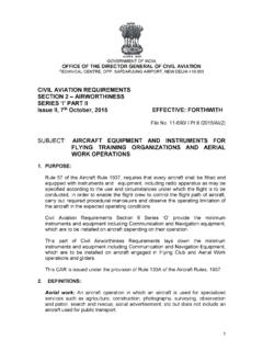
5 The potentiometer control shafts are easily damaged after the hex nuts have been Attach the intercom/control panel assembly to the aircraft panel with four 6-32 non-magnetic Attach the Volumeand Squelchcontrol knobs to the screws, so that both knobs point to the 7 o clock position when rotated completely PanelLargeControl Panel6-32 Non-magnetic Screws (4)Knobs (2)VOLUMESQUELCHINTERCOMHex Nuts & Washers(2 each)Figure 2 - Large Control Panel-Exploded View INTERCOMAIRCRAFTPANELW ashers (2)Nuts (2)Knobs(2)6-32 Non-MagneticScrews (4)Through-panel or Under-panel MountingThe intercom can be mounted in any inch deep, inch by inch space.
6 It can be placed either verti-cally or horizontally in or under the aircraft instrument panel or in any other accessible location in the through-panel or under-panel mounting:1. Leave the two potentiometer nuts in place on the Place the small intercom control panel on the aircraft panel either vertically or horizontally (page 2, Figure 3),and use one of the drill templates shown in (Figure 4, page 2)to trace the location of the holes for drilling. For panels less than .1 inch thick, use a 9/32 inch drill bit for the controls (use Drill Template #1 in Figure 4, page 2,).
7 For panels between .1 and .2 inches thick, use a 1/2 inch drill bit or punch to clear the potentiometer nuts (use Drill Template #2 in Figure 4, page 2). Figure 2- Large Control Panel-Exploded View13 Insert the intercom through the aircraft panel and the small intercom control panel with the correct side Attach the intercom and control panel to the aircraft panel using two 4-40 by 1/2 inch mounting Attach the Volume andSquelchcontrol knobs so that they both point to the 7 o clock position when they are rotated completely :to avoid contact with parts inside the intercom, do not use screws longer than 1/2 inch.
8 INTERCOMAIRCRAFTPANELKnob4-40 Non-MagneticScrews (2)KnobDO NOTR emoveThese ".4".4".3".3"9/32"9/32"3/16"1/4"3/16".18 5".4".4".3".3"3/16"1/4"3/16"1/2"1/2"Figu re 4- Drill TemplatesFigure 3- Small Intercom Faceplate InstallationHeadphone and Microphone Jack InstallationThe 403 and 403d intercoms can be installed as either a stereo/monaural, monaural only, or stereo only either type of installation you may leave the existing aircraft headphone and microphone jacks in place touse as a convenient tie in point at which to connect wires 8, 17, and 21 to the radio, or you may connect theintercom to an audio panel instead of the aircraft jacks.
9 You can also use the existing jacks as a standby radioconnection if you remove the intercom for all three types of installation , you must insulate the microphone jacks from the airframe, but you may eitherground the headphone jacks to the airframe or insulate them with a separate ground wire running back to :do not use the same ground wire for headphone and microphone jacks, even when the ground wiresare connected at the same location on the Jack InstallationThe stereo/monaural installation is preferable because it allows stereo and monaural headsets to be used at thesame time.
10 To attach headphone and microphone jacks to the aircraft panel when you are installing the intercom as astereo/monaural system:1. Choose an accessible location in the aircraft panel for each pair of headphone and microphone jacks (one pair each for the pilot and co-pilot and one pair each for up to four passengers).2. Using the stereo/mono switch plate as a template placed either horizontally or vertically, carefully mark each stereo/mono switch and headphone jack Drill one 1/4 inch hole in the aircraft panel for each stereo/mono switch and one 3/8 inch hole for each headphone jack (Figure 5 below).