Transcription of Installation/Owner’s Manual Series 6500Series 6500
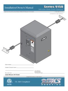
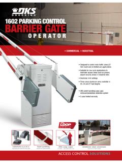
1 installation / owner s ManualSeries 6500 Series 6500 Series 6500 Copyright 2009 DoorKing, Inc. All rights 2014 DoorKing, Inc. All rights Installed:Installer/Company Name:Phone Number:Leave Manual with owner Vehicular Swing Gate OperatorUL 325 CompliantCircuit BoardSerial Numberand Revision Letter:Use this Manual for circuit board 4405-010 Revision E or 6500-065-W-3-141 Class of Operation Model 6500 - UL325 Class I, II, III, IV Type of Gate Vehicular Swing Gates Only Entrapment Protection Primary - Inherent entrapment sensing system (Type A) Secondary - Provision for connection of a non-contact sensor (Type B1)SPECIFICATIONS 28 3/8 18 3/8 23 1/4 31 5/8 31 Model #Max GateWeightMax GateLengthHorsepower - Volts1/2 HP - 115 VAC1/2 HP - 115 VAC1/2 HP - 115 VAC1/2 HP - 115 VAC1 HP - 115 VAC1 HP - 115 VAC1 HP - 115 VAC1 HP - 115 VAC1-Phase1-Phase1-Phase1-Phase1-Phase1- Phase1-Phase1-Phase6500-0806500-0816500- 0826500-0836500-0846500-0856500-0866500- 087600 PerHour6060606060606060 Speed90 12-14 Sec12-14 Sec12-14 Sec12-14 Sec12-14 Sec12-14 Sec12-14 Sec12-14 this Manual for the Model 6500 operators with circuit board 4405-010 Rev E or higher , Inc.
2 Reserves the right to make changes in the products described in this Manual without notice and without obligation of DoorKing, Inc. to notify any persons of any such revisions or changes. Additionally, DoorKing, Inc. makes no representations or warranties with respect to this Manual . This Manual is copyrighted, all rights reserved. No portion of this Manual may be copied, reproduced, translated, or reduced to any electronic medium without prior written consent from DoorKing, : 208/230/460/575 VAC input voltage can be connected to the operator by installing an Optional High Voltage Kit (P/N 2600-266). 6500-065-W-3-142 SPECIFICATIONS1 ASTM F2200 Standard for Gate ConstructionImportant Safety InstructionsInstructions regarding intended installation :Important NoticesUL 325 Entrapment ProtectionGlossarySwing Gate RequirementsSwing Gate Protection44456789 SECTION 1 - Underground Conduit Concrete Type of Securing Operator to Attach Gate Determining Arm installation of Warning Signs SECTION 2 - AC POWER TO OPERATOR(S)
3 High Voltage Wire High Voltage Terminal Bi-Parting Gates Wiring - Dual Gate OperatorsSECTION 3 - 4405 Circuit Board Descriptions and DIP-Switch Settings for 4405 Circuit Limit Inherent Reverse Sensors Secondary Current Sensor Adjustment1818-19202122 TABLE OF CONTENTS 6500-065-W-3-143 SECTION 4 - ENTRAPMENT AND SAFETY UL 325 Terminal Entrapment and Safety Protection Device Loop Detector WiringSECTION 5 - MAIN TERMINAL Terminal Control WiringSECTION 8 - MAINTENANCE AND Built-in Accessory Gearbox Shaft Extension ReplacementModel 6500 s Wiring Diagrams3435-3637383940-45 SECTION 6 - OPERATING Power and Reset Shutdown ConditionsSoft ShutdownHard Manual Gate OperationEmergency Vehicle Access ConditionsManual Release312829-30 SECTION 7 - OPTIONAL CONVENIENCE OPEN Operating DC System DIP-Switch Settings for 2340 Circuit Board32333332 TABLE OF CONTENTS 6500-065-W-3-144 Instructions regarding intended installation : Vehicular gates should be constructed and installed in accordance with ASTM F2200; Standard Specification for Automated Vehicular Gate Construction.
4 For a copy of this standard, contact ASTM directly at 610-832-9585; or Safety Instructions WARNING - To reduce the risk of injury or death:1. READ AND FOLLOW ALL Never let children operate or play with gate controls. Keep the remote control away from Always keep people and objects away from gate. NO ONE SHOULD CROSS THE PATH OF THE MOVING Test the operator monthly. The gate MUST reverse on contact with a rigid object or stop or reverse when an object activates the non-contact sensors. After adjusting the force or the limit of travel, retest the gate operator. Failure to adjust and retest the gate operator properly can increase the risk of injury or Use the emergency release only when the gate is not KEEP GATES PROPERLY MAINTAINED. Read the owner 's Manual . Have a qualified service person make repairs to gate The entrance is for vehicles only. Pedestrians must use separate SAVE THESE INSTRUCTIONS! Install the gate operator only if: 1. The operator is appropriate for the construction of the gate and the usage class of the gate.
5 2. All openings of a horizontal slide gate are guarded or screened from the bottom of the gate to a minimum of 6 feet ( m) above the ground to prevent a 2 inch ( mm) diameter sphere from passing through the openings anywhere in the gate, and in that portion of the adjacent fence that the gate covers in the open position. 3. All exposed pinch points are eliminated or guarded. 4. Guarding is supplied for exposed rollers. The operator is intended for installation only on gates used for vehicles. Pedestrians must be supplied with a separate access opening. The pedestrian access opening shall be designed to promote pedestrian usage. Locate the gate such that persons will not come in contact with the vehicular gate during the entire path of travel of the vehicular gate. The gate must be installed in a location so that enough clearance is supplied between the gate and adjacent structures when opening and closing to reduce the risk of entrapment.
6 Swinging gates should not open into public access areas. The gate must be properly installed and work freely in both directions prior to the installation of the gate operator. Do not over-tighten the operator clutch, pressure relief valve or reduce reversing sensitivity to compensate for a damaged gate. For gate operators utilizing Type D protection: 1. The gate operator controls must be placed so that the user has full view of the gate area when the gate is moving. 2. A warning placard shall be placed adjacent to the controls. 3. An automatic closing device (such as a timer, loop sensor, or similar device) shall not be employed. 4. No other activation device shall be connected. Controls intended for user activation must be located at least ten feet (10 ) away from any moving part of the gate and where the user is prevented from reaching over, under, around or through the gate to operate the controls. Outdoor or easily accessible controls should have a security feature to prevent unauthorized use.
7 The Stop and/or Reset button must be located in the line-of-sight of the gate. Activation of the reset control shall not cause the operator to start. A minimum of two (2) WARNING SIGNS shall be installed, one on each side of the gate where easily visible. For gate operators utilizing a non-contact sensor: 1. See the instructions on the placement of non-contact sensors for each type of application. 2. Care shall be exercised to reduce the risk of nuisance tripping, such as when a vehicle trips the sensor while the gate is still moving in the opening direction. 3. One or more non-contact sensors shall be located where the risk of entrapment or obstruction exist, such as the perimeter reachable by a moving gate or F2200 Standard for Gate Construction 6500-065-W-3-145 For gate operators utilizing contact sensors: 1. One or more contact sensors shall be located where the risk of entrapment or obstruction exist, such as at the leading edge, trailing edge, and post mounted both inside and outside of a vehicular horizontal slide gate.
8 2. One or more contact sensors shall be located at the bottom edge of a vehicular vertical lift gate. 3. One or more contact sensors shall be located at the pinch point of a vehicular vertical pivot gate. 4. A hardwired contact sensor shall be located and its wiring arranged so that the communication between the sensor and the gate operator is not subjected to mechanical damage. 5. A wireless contact sensor such as one that transmits radio frequency (RF) signals to the gate operator for entrapment protection functions shall be located where the transmission of the signals are not obstructed or impeded by building structures, natural landscaping or similar obstructions. A wireless contact sensor shall function under the intended end-use conditions. 6. One or more contact sensors shall be located at the bottom edge of a vertical barrier (arm). Vehicular gate operator products provide convenience and security.
9 However, gate operators must use high levels of force to move gates and most people underestimate the power of these systems and do not realize the potential hazards associ-ated with an incorrectly designed or installed system. These hazards may include: Pinch points Entrapment areas Reach through hazards Absence of entrapment protection devices Improperly located access controls Absence of vehicle protection devices Absence of controlled pedestrian accessIn addition to these potential hazards, automated vehicular gate systems must be installed in accordance with the UL 325 Safety Standard and the ASTM F2200 Construction Standard. Most lay persons are unaware of, or are not familiar with, these standards. If an automated vehicular gate system is not properly designed, installed, used and maintained, serious injuries or death can result. Be sure that the installer has instructed you on the proper operation of the gate and gate operator sure that the installer has trained you about the basic functions of the required reversing systems associated with your gate operating system and how to test them.
10 These include reversing loops, inherent reversing system, electric edges, photoelectric cells, or other external devices. This owner s Manual is your property. Keep it in a safe place for future reference. Be sure that all access control devices are installed a minimum distance of 10 feet away from the gate and gate operator, or in such a way that a person cannot touch the gate or gate operator while using the device. If access control devices are installed in violation of these restrictions, immediately remove the gate operator from service and contact your installing dealer. Loops and loop detectors, photo-cells or other equivalent devices must be installed to prevent the gate from closing on vehicular traffic. The speed limit for vehicular traffic through the gate area is 5 MPH. Install speed bumps and signs to keep vehicular traffic from speeding through the gate area. Failure to adhere to posted speed limits can result in damage to the gate, gate operator, and to the vehicle.