Transcription of Installation Procedure and Wheel Bearing ... - STEMCO
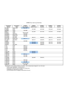
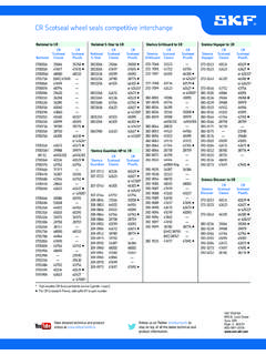
1 1an EnPro Industries companyHERRAMIENTAS NECESARIAS PARA LA INSTALACI NNo. de ParteDado RequeridoTuerca para Eje de Remolque447-4723 Dado octagonal de 4 13/16 pulg447-4724 Tuerca para Eje de Remolque447-4743 Dado octagonal de 3 3/4 pulg449-4973 Dado hexagonal de 4 3/8 pulgTuerca para Eje de Tracci n449-4904 Dado hexagonal de 4 1/8 pulg449-4973 Dado hexagonal de 4 3/8 pulg449-4974 Dado hexagonal de 3 3/4 pulg449-4975 Dado hexagonal de 3 3/4 pulgNo. de ParteDado RequeridoTuerca para Eje de Direcci n448-4836 Dado hexagonal de 2 1/2 pulg448-4837448-4838448-4839 Dado hexagonal de 2 5/8 pulg448-4840 Dado hexagonal de 2 1/2 pulg448-4863 Dado hexagonal de 3 1/2 pulg448-4864 Dado hexagonal de 3 pulg448-4865 Dado hexagonal de 3 pulgNota: La aplicaci n del eje de direcci n SIFCO para Ford de 12,000 lb, requiere de una roldana interna de equipo original que debe instalarse antes de colocar el sistema de tuerca PRO-TORQ. TOOLS REQUIRED FOR INSTALLATION450-4743 Updated DesignProtrusion feature(Prevents backward Installation )Same slot for Numbers(3/4 Drive) Socket Req Co.
2 Ref. Part Int l. Ref. Part Axle Nut447-47234 13/16 8 point1941E-1597447-4724 Trailer Axle Nut447-47433 3/4 8 point1925E-1925449-49734 3/8 8 point1917E-1917 Drive Axle Nut449-49044 1/8 6 point1915E-1915449-49734 3/8 8 point1917E-1917449-49743 3/4 8 point1925E-1925449-49753 3/4 8 point1925E-1925 Part Numbers(3/4 Drive) Socket Req Co. Ref. Part Int l. Ref. Part Spindle Nut448-48362 1/2 6 point1921E-1921448-4837448-4838448-48392 5/8 6 point1922E-1922448-48402 1/2 6 point1921E-1921448-48633 1/2 6 point19202 1/2-12448-48643 6 point1906E-1906448-48653 6 point1906E-1906 Note: Ford application 12,000 lbs. SIFCO Steer Axle requires OEM inner washer to be installed prior to Installation of PRO-TORQ nut Procedure and Wheel Bearing AdjustmentProc dure d Installation et Ajustement du RoulementPRO-TORQ Installation CHARTPRO-TORQ TABLA DE INSTALACI NWARNINGF ailure to follow this instruction could cause the Wheel to come off and cause bodily injury.
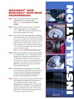
3 Failure to back off the nut will cause the Bearing to run hot and be THE KEEPER FROM THE NUT:Use a small screwdriver to carefully pry the keeper arm from the undercut groove on each side until the keeper is 1 Thread the nut onto the axle until hand tight against the 2 SEAT THE Bearing :With hub or hub/drum only:Using a torque wrench:A (1) Tighten the nut to 200 ft-lbs. Spin the Wheel at least one full rotation. (2) Tighten the nut to 200 ft-lbs. Spin the Wheel at least one full rotation. (3) Tighten the nut to 200 Back the nut off until it is hub/drum/wheels:A Tighten the nut to 200 ft-lbs while the Wheel is Back the nut off until it is 3 STEP 4 ADJUST THE Bearing :With hub or hub/drum only:Using a torque wrench:A (1) Tighten the nut to 100 ft-lbs. Spin the Wheel at least one full rotation. (2) Tighten the nut to 100 ft-lbs. Spin the Wheel at least one full rotation. (3) Tighten the nut to 100 Back the nut off one raised face mark (according to chart).
4 With hub/drum/wheels:Using a torque wrench:A Tighten the nut to 100 ft-lbs while the Wheel is Back the nut off one raised face mark (according to chart).STEP 5 INSTALL THE KEEPER: ORANGE SIDE FACING OUTA Insert the keeper tab into the undercut groove of the nut and engage the keyway tang in the axle keyway. Insert keeper tab with the orange side facing Engage the mating Compress and insert the keeper arms, one at a time, into the undercut groove with a small STEERING SPINDLE NUT 448-4836, 448-4839, 448-4840, 448-4863, 448-4864 & 448-4865:A Align the flat of the keeper with the milled flat on the spindle and insert the keeper tab into the undercut groove of the nut. Insert keeper tab with the orange side facing Engage the mating Compress and insert the keeper arms, one at a time, into the undercut groove with a small the inner tang does not line up with the keyway, back the nut off slightly until it does. Using a small screwdriver, compress and insert the keeper arms, one at a time, into the undercut groove.
5 The orange painted side of the keeper must be facing 6 STEP 7 Failure to follow this instruction could cause the Wheel to come off and cause bodily injury. Make sure that the keeper tab and keeper arms are fully seated into the undercut groove. STEP 8 Inspect keyway tang to insure it does not contact the bottom of the keyway. If contact exists, immediately notify your PRO-TORQ 9 ACCEPTABLE END PLAY:The dial indicator should be attached to the hub or brake drum with its magnetic base. Adjust the dial indicator so that its plunger is against the end of the spindle with its line of action approximately parallel to the axis of the the Wheel or hub assembly at the 3 o clock and 9 o clock positions. Push and pull the Wheel -end assembly in and out while oscillating the Wheel approximately 45 degrees. Stop oscillating the hub so that the dial indicator tip is in the same position as it was before oscillation began. Read the Bearing end-play as the total indicator movement.
6 *Acceptable end-play is .001 .005 For single nut self-locking systems, consult manufacturers specifications. STEMCO assumes no responsibility for other manufacturers' Bearing : Recommended practice is to replace the keeper each time the Pro-Torq nut assembly is removed for maintenance seguir estas instrucciones puede provocar que la rueda se salga del eje ocasionando serios accidentes. No aflojar la tuerca seg n el procedimiento indicado causar que los rodamientos se sobre-calienten y se da - USA Box 1989 Longview, TX 75606-1989 (903) 758-9981 1-800-527-8492 FAX: 1-800-874-4297 - Canada 5650 Timberlea Blvd. Unit B Mississauga, ON L4W 4M6 (905) 206-9922 877-232-9111 FAX: 877-244-4555 STEMCO - Australia Unit 6 CNR Rookwood & Muir Roads Yagoona NSW 2199 Phone: 011-61-2-9793-2599 FAX: 011-61-2-9793-2544 ISO 16949 STEMCO and Pro-Torq are registered trademarks of STEMCO LP 2016 STEMCO LPPrinted in the USA Part No.
7 571-2994 Rev. 1/16 ASENTAR LOS RODAMIENTOS:Con maza, o maza/tambor solamente: Utilizando un torqu metro:A (1) Apriete la tuerca hasta 200 lbs - pi . Gire la rueda por lo menos una vuelta completa. (2) Apriete la tuerca hasta 200 lbs - pi . Gire la rueda por lo menos una vuelta completa. (3) Apriete la tuerca hasta 200 lbs - pi .B Afloje la tuerca hasta que quede maza/tambor/rueda:A Apriete la tuerca a 200 lbs - pi mientras gira la Afloje la tuerca hasta que quede 3Si la leng eta no se alinea con la ranura del eje, afloje ligeramente la tuerca hasta que lo haga. Comprima el seguro, y utilizando un desarmador peque o, inserte uno por uno los brazos del seguro dentro de la ranura de la tuerca. Aseg rese que la parte anaranjada quede hacia 6 PASO 4 AJUSTE DEL RODAMIENTO:Con maza, o maza/tambor solamente: Utilizando un torqu metro:A (1) Apriete la tuerca hasta 100 lbs - pi . Gire la rueda por lo menos una vuelta completa.
8 (2) Apriete la tuerca hasta 100 lbs - pi . Gire la rueda por lo menos una vuelta completa. (3) Apriete la tuerca hasta 100 lbs - pi .B Afloje la tuerca un punto marcado en la tuerca (de acuerdo con el diagrama).Con maza/tambor/rueda: Utilizando un torqu metro:A Apriete la tuerca hasta 100 lbs - pi mientras gira la Afloje la tuerca un punto marcado en la tuerca (de acuerdo con el diagrama).PASO 5 INSTALACI N DEL SEGURO: EL LADO ANARANJADO DEBE ESTAR HACIA AFUERAA Inserte la leng eta del seguro en el ranura maquinada de la tuerca y enc jela en la ranura correspondiente del eje. Inserte la leng eta del seguro con la parte anaranjada hacia Encaje los Comprima el seguro, y utilizando un desarmador peque o, inserte uno por uno los brazos del seguro dentro de la ranura de la LAS TUERCA DE LOS EJES DE DIRECCI N CON NO. DE PARTE 448-4836, 448-4839, 448-4840, 448-4863, 448-4864 & 448-4865:A Alinee el plano del seguro con el plano de la parte maquinada del eje.
9 Inserte la leng eta del seguro en la ranura maquinada de la tuerca. Inserte la leng eta del seguro con la parte anaranjada hacia Encaje los Comprima el seguro, y utilizando un desarmador peque o, inserte uno por uno los brazos del seguro dentro de la ranura de la 7No seguir estas instrucciones puede provocar que la rueda se salga del eje ocasionando serios accidentes. Aseg rese de que la leng eta y los brazos del seguro est n totalmente encajados en el ranura maquinada de la 8 Inspeccione la leg eta para asegurarse de que no haga contacto con el fondo de la ranura maquinada del eje. Si existe contacto, notifique inmediatamente a su representanet de PRO-TORQ .PASO 9 JUEGO AXIAL ACEPTABLE DE LA RUEDA:El lector de car tula debe adherirse a la maza o al tambor utilizando su base magn tica. Ajuste el indicador de car tula de manera que la punta quede contra el final del eje, y su l nea de acci n paralela a la la rueda o la maza en la posici n de las 3 y las 9 horas.
10 Jale y empuje hacia adentro y hacia afuera todo el ensamblaje y gire la rueda hacia un lado y hacia el otro en un rango de aproximadamente 45 grados. Pare la rueda de manera que la punta del indicador quede en la misma posici n que estaba antes de empezar el movimiento. El juego axial final de los rodamientos es indicado por el movimiento total de la aguja en el indicador de car tula. *El juego axial aceptable es de .001 .005 Para sistemas de una sola tuerca con seguro integrado, siga las recomendaciones del fabricante. STEMCO no asume responsabilidad por la garant a de rodamientos de otras : Es recomendado cambiar el seguro cada vez que la tuerca se quite por motivos de EL SEGURO DE LA TUERCA:Utilice un desarmador peque o para desalojar cuidadosamente el brazo del seguro de la ranura en cada lado, hasta que se suelte el 1 Instale la tuerca sobre el eje hasta que se ajuste contra el 2 3A 3B 4A 4B FINAL BACKOFF AJUSTE FINAL PART NUMBER BACKOFF Trailer Axle Nut 447-4723 447-4724 1/8 turn 449-4973 Trailer Axle Nut 447-4743 1/4 turn Steering Spindle Nut 448-4836 448-4838 448-4839 1/4 turn 448-4863 448-4864 448-4865 Steering Spindle Nut 448-4837 1/3 turn 448-4840 Drive Axle Nut 449-4904 449-4973 1/8 turn 449-4974 449-4975 NO.