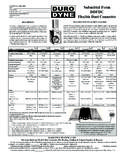
Transcription of Installation Requirements - Flexible Duct
1 Installation Requirements Code Reference The authority having jurisdiction should be referenced to determine what law, ordinance or code shall apply in the use of Flexible duct . Ducts conforming to NFPA 90A or 90B shall meet the following Requirements : a. Shall be tested in accordance with Sections 7 to 23 of Underwriters Laboratories Standard for Factory-Made Air Ducts and Air Connectors, UL 181. b. Shall be installed in accordance with the conditions of their listing. c. Shall be installed within the limitations of the applicable NFPA 90A or 90B Standard. Installation Restrictions and Use Limitations There are specific restrictions and limitations related to the use of Flexible ducts.
2 Some are due to NFPA Standards, model codes and various state/local codes. Others are due to end use performance where the product was not designed for that specific use. Some, but not all inclusive, are as follows: a. Shall not be used for vertical risers serving more than two stories in height. b. Shall not be used in systems with entering air temperature higher than 250 F[121 C]. c. Shall be installed in accordance with the conditions of their listing. d. When installed in a fire-rated floor/roof ceiling assembly, ducts shall conform with the design of the tested fire-resistive assembly. e. Shall be interrupted at the immediate area of operation of electric, fossil fuel or solar energy collection heat sources to meet listed equipment clearances specified.
3 4 9 ADC Flexible duct Performance & Installation Standards, 5th Edition f. Air Connectors (does not apply to Air Ducts) shall not be installed in lengths greater than 14 ft. [ m] for any given run; shall not pass through any wall, partition or enclosure of a vertical shaft with a 1 hour or more fire resistive rating; shall not pass through floors. g. Shall not penetrate walls where fire dampers are required. h. Shall not be used outdoors unless specifically designed to withstand exposure to direct sunlight and the weathering elements. i. Shall not be used to vent appliances for cooking, heating and clothes drying unless approved and recommended by the appliance manufacturer. j. Shall not be installed in concrete, buried below grade or in contact with the ground.
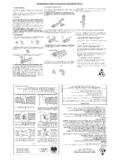
4 General The routing of Flexible duct , the number of bends, the degrees in each bend, and the amount of sag or direction changes (snaking) allowed between support joints will have serious effects on system performance due to the increased resistance each introduces (See Fig 6 & 7). Use the minimum length of Flexible duct to make connections (See Section ). Excess length of Flexible duct shall not be installed to allow for possible future relocations of air terminal devices. Avoid installations where exposure to direct sunlight can occur, turbine vents, sky lights, canopy windows, etc. Prolonged exposure to sunlight will cause degradation of the vapor barrier.
5 Direct exposure to UV light from a source lamp installed within the HVAC system will cause degradation of some inner core/liner materials. Terminal devices shall be supported independently of the Flexible duct . Repair torn or damaged vapor barrier/jacket with duct tape listed and labeled to Standard UL 181B. If internal core is penetrated, replace Flexible duct or treat as a connection. Installation Requirements .. continued Do not bend ducts across a sharp corner of building materials such as joists or truss supports. The bend radius at the center line of ducts shall be equal to or greater than one duct diameter (See Figures 8 and 11).
6 Sharper bends increase pressure drop significantly and reduce airflow. Avoid incidental contact with metal fixtures, water lines, pipes, or conduits. Do not install near hot equipment ( furnaces, boilers, steam pipes, etc.) that is above the recommended Flexible duct use temperature. Figure 9 - Incorrect. Contact with steam pipes. 10 ADC Flexible duct Performance & Installation Standards, 5th Edition Figure 8 - Correct. Minimum 1 duct diameter bend radius reduces pressure drop and improves air flow. Installation and Usage Install ducts fully extended. Do not install in the compressed state or use excess length as this will noticeably increase friction losses.
7 (Refer to Section for more specific information regarding pressure loss and duct sizing.) Figure 6 - Minimum duct length and bend radius reduces pressure drop and improves airflow. Figure 7 - Excess length and tight bend radius increases pressure drop and reduces airflow. duct Sizing and Routing The combined friction and dynamic pressure losses shall be taken into consideration to properly size any duct . Pressure losses caused by the roughness of the duct wall resisting air movement are know as friction losses. Pressure losses when air flow changes direction, as caused by bends or when air flows across other system components, are known as dynamic losses.
8 Key points to prevent undersizing or oversizing of Flexible ducts and achieve the designed air delivery performance: a. Use a proven method of duct sizing, one that has taken into consideration both friction and dynamic losses. Design the Flexible duct system per the Requirements of ACCA, Manual D (Residential) and Manual Q (Commercial). Properly take into account duct length, bend losses, sagging or routing expectations, fitting losses, etc. b. Have a good understanding of and properly use the air friction chart. Do not use data for round sheet metal duct . Since all Flexible ducts are not alike, use the Flexible duct manufacturer s air friction loss data to size the ducts whenever possible.
9 If no data is available, use the generic Flexible duct friction loss chart in ACCA Manual D. c. Use the minimum length of Flexible duct needed to make the connections. Install ducts extended to their fullest length without compression. Due to the helical configuration of Flexible duct inner cores, excess longitudinal compression can dramatically affect the pressure drop. If a Flexible duct is not fully extended, the friction rate increases proportionally with the compression (See Fig. 10). When a Flexible duct is fully extended, it is said to have no more than 4% longitudinal compression and the published friction rate may be used for duct sizing calculations (0 - 4% = 1 x Friction Rate).
10 For 15% longitudinal compression the friction rate can increase by a factor of two (15% = 2 x Friction Rate). For longitudinal compression of 30% the friction rate can increase as much as four times (30% = 4 x Friction Rate). Figure 10 - Compressed duct (not fully ex-tended) increases friction rate. 11 ADC Flexible duct Performance & Installation Standards, 5th Edition Installation Requirements .. continued Figure 11 d. Keep bends greater than or equal to one (1) duct diameter bend radius. 12 ADC Flexible duct Performance & Installation Standards, 5th Edition Installation Requirements .. continued e. Properly route and support the Flexible duct runs. Figure 12 Care shall be taken to minimize sagging or snaking of the duct between supports and minimize pressure loss caused by excessive direction changes to the airflow.