Transcription of Installation/User Guide Operation & Maintenance …
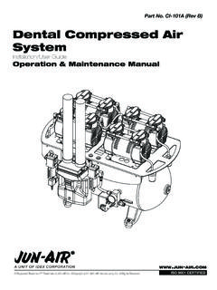
1 Part No. CI-100A (Rev B)Dental Vacuum Suction SystemInstallation/ user GuideOperation & Maintenance Manual Registered Trademark/ Trademark of JUN-AIR Inc. Copyright 2012 JUN-AIR Manufacturing Inc. All Rights 9001 CERTIFIED2CI-100A (Rev B) JUN-AIR Dental Vacuum Suction System user Guide 2012, JUN-AIRWe reserve the right to make any alterations which may be due to any technical improvementsPrinted in the USATABLE OF CONTENTSI mportant Safety Instructions and Regulatory Information ..2-4 System features ..5 Unpacking ..7 installation Safety Data ..8 Site Requirements ..10 Plumbing ..11 installation - Below Grade ..13 installation - Above Grade ..14 Electrical ..15 Checks and tests ..16 Operation ..17 Maintenance ..18 Specifications ..19 Troubleshooting Chart ..20-22 Options & Accessories.
2 23 Warranty ..23 installation Checklist ..24 WARNINGPLEASE READ THIS MANUAL COMPLETELY BEFORE INSTALLING AND USING THIS PRODUCT. SAVE THIS MANUAL FOR FUTURE REFERENCE AND KEEP IN THE VICINITY OF THE Customer:Congratulations on the purchase of your new JUN-AIR Dental Vacuum Suction System . This system s intended purpose is for dental suction applications . It is to be used in accor-dance with UL60601-1 and NFPA 99C stan-dards, along with all applicable codes . The sys-tem utilizes a dry vacuum regenerative blower that produces high air flow when connected to the dental operatory lines . IMPORTANT SAFETY INSTRUCTIONSA vacuum relief valve is also included to maxi-mize the system s efficiency by holding a con-stant vacuum level . This manual provides instal-lation, Operation and preventative Maintenance guidelines that should be followed to ensure correct/reliable performance of this system.
3 3 2012, JUN-AIRWe reserve the right to make any alterations which may be due to any technical improvementsPrinted in the USAJUN-AIR Dental Vacuum Suction System user Guide CI-100A (Rev B)TABLE OF SYMBOLS CAUTION: Indicates a potentially hazardoussituation which may result in minor ormoderate injury if not avoided. It may also beused to alert against unsafe : To Avoid Serious Burns:Do not touch surface during the ON and OFF position for the Equipment power Switch ON OFFIOI ndicates package should be handled with these symbols pointing up. FRAGILE: Handle package with care. Indicates this package must be kept the acceptable shipping temperature range. -29 C-20 F+50 C+122 FIndicates the acceptable maximum relative humidity for the acceptable lowest barometricpressure conditions in which this unit canbe ATM4CI-100A (Rev B) JUN-AIR Dental Vacuum Suction System user Guide 2012, JUN-AIRWe reserve the right to make any alterations which may be due to any technical improvementsPrinted in the USAINTENDED USE:To provide suction during general dental examina-tions and procedures conducted by qualified dental vacuum systems meet or exceed the most current and highest safety standards, which are: CSA (2005) UL60601-1 classified revision 2006/04/26 - Classification: Class I, permanently fixed MAINS operated equipment NFPA 99C level 3 gas system requirements compliance revision 2005 NFPA 70 (National Electric Code) revision 2008 ISO 9001.
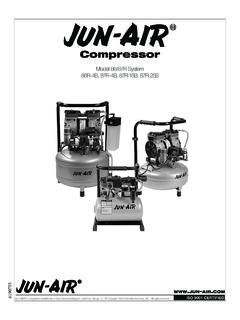
4 2008 Ingress protection: IPX0To ensure the safety potential of this equip-ment is achieved, please:Make sure your equipment is installed according to the instructions provided in this manual and make sure the installation checklist is completed prior to starting the is not suitable for use in the presence of a flammable anesthetic mixture containing air/oxygen or nitrous oxide. DO NOT OPERATE THE EQUIP-MENT IF THESE CONDITIONS against electrical shock:Provide proper grounding per NFPA 70 (NEC 2008). Do not become a current path for the equipment to ground through your Conditions: Temperature range C to 50 C / -20 F to 122 F Relative Humidity 95% (non-condensing) Barometric pressure minimum of 372 mm Hg (.49 atm)Do not stack units during shipment/storage or : Refer servicing to an authorized service INFORMATION5 2012, JUN-AIRWe reserve the right to make any alterations which may be due to any technical improvementsPrinted in the USAJUN-AIR Dental Vacuum Suction System user Guide CI-100A (Rev B)SYSTEM FEATURESI nlet From OperatorySystem Check Valve(3) Lid KnobsVacuum Relief Valve(Any required adjustments are onlyto be made by an authorized distributor.)
5 Improper adjusment will cause overheatingand failure.)Drainage Elbow/Check ValveDrain2 X Cabinet FansExhaust From Blower6CI-100A (Rev B) JUN-AIR Dental Vacuum Suction System user Guide 2012, JUN-AIRWe reserve the right to make any alterations which may be due to any technical improvementsPrinted in the USASYSTEM FEATURESS eparation TankTank Support FrameSound EnclosureElectrical Panel CoverHour Meter4 X Leveling FeetSystem BreakerPower On Indicator LightLow Pressure HoseVacuum Gauge7 2012, JUN-AIRWe reserve the right to make any alterations which may be due to any technical improvementsPrinted in the USAJUN-AIR Dental Vacuum Suction System user Guide CI-100A (Rev B)UNPACKING1. Examine contents for damage prior to removing shipping carton. a. If shipping damage is found, immediately contact the freight carrier to file a Carefully remove the shipping carton from the pallet containing the vacuum Visually inspect the entire vacuum system for shipping damage.
6 A. If shipping damage is found, immediately contact the freight carrier and supplier. 4. Verify that the installation kit parts were shipped with the system: a. installation kit parts shipped with all vacuum system models include the following: (3) Hose barbs (6) Hose clamps (3) Low pressure intake hoses ( inches in length) (1) O&M Manual5. Remove the installation kit parts and set aside until the unit is ready to be Remove the (8) 5/16 in carriage bolts and the four shipping brackets from the sound Remove the (3) 5/16 in carriage bolts from the tank support Remove the band strap from foam3 x 5/16 incarriage bolts8 x 5/16 incarriage bolts4 x "Hose ClampHose BarbHose WARNING: DO NOT install on surfaces with more than a 5 incline. WARNING: Fasten unit to shipping pallet prior to transporting the equipment to prevent tipping or (Rev B) JUN-AIR Dental Vacuum Suction System user Guide 2012, JUN-AIRWe reserve the right to make any alterations which may be due to any technical improvementsPrinted in the USAPERSONAL SAFETY: DANGER: Danger of fire or explosion when using flammable substances.
7 Do not operate the vacuum system in an area containing combustible gases or anesthetic mixtures. CAUTION: Do not place vacuum system within 6 feet of patient. CAUTION: Never leave children unattended near vacuum system when in use. WARNING: Property damage and/or personal injury may result if directions are not followed or manufacturer s replacement parts/accessories are not used. WARNING: Connect only equipment suitable for listed maximum vacuum level of the blower. Equipment is not suitable for use in vital (continuation of life) operations , an alternative air source should be used in these instances. WARNING: A leaking vacuum relief valve may indicate a need for adjustment or repair. Any required adjustments are only to be made by an authorized distributor. Improper adjustment will cause overheating and : Indoor use only in dust free, climate controlled room.
8 DO NOT install in an enclosed area where ambient temperature could exceed temperature specifications of below C / 40 F, or above 40 C / 104 F while the vacuum system is run-ning. Maintain minimum 6 inches of clearance around system. Maintain 12 inches of clearance on top of system. Vacuum systems are equipped with 4 adjust-able feet, to ensure unit stands firmly on the floor. Level the system in two plains prior to starting system. Assure proper external exhaust ventilation prior to starting the system (see SPECIFICATIONS). installation SAFETY DATAI ndicates the ON and OFF position for the equipment power switch (system breaker)When ON, the indicator light will illuminate and voltage WILL be supplied to OFF, the indicator light will NOT illuminate and voltage WILL NOT be supplied to the system. Io= ON= OFFIoEquipment Alert: Vacuum system must be installed per local plumbing and electrical 2012, JUN-AIRWe reserve the right to make any alterations which may be due to any technical improvementsPrinted in the USAJUN-AIR Dental Vacuum Suction System user Guide CI-100A (Rev B) CAUTION: Routinely inspect any and all power cords for cuts and abrasions.
9 Discontinue use and have authorized service representative replace cord if damaged. ELECTRICAL SAFETY: Follow NEC, NFPA 99C and all applicable local codes. Systems are shipped with appropriate electrical conduit to hardwire into stand alone breaker. Qualified personnel must install electrical wiring and outlets. Unit requires a dedicated (separate branch circuit only) 30 amp circuit, 230 VAC. Never operate unit outside the specified voltage range 208-253 VAC. (see page 15, installation - ELECTRICAL ) See SPECIFICATIONS for more electrical information. There is an indicator light on the system which indicates the power is INTERFERENCE (EMI):The JUN-AIR vacuum suction system is designed to avoid electromagnetic emissions/interference with surrounding electrical equipment. Due to the vast assortment of electrical equipment available, it is possible that some interference may be experienced by the end customer.
10 If interference is experienced, the device that is creating interference should be removed from the room where the vacuum system is located. If the interference persists, then it may be necessary to confirm that both devices are connected to isolated (separated) circuits per ELECTRICAL installation INSTRUCTIONS in this manual. If the problem still occurs, then the two devices should be moved as far apart as possible. Finally, if the problem can not be eliminated, contact an authorized SAFETY DATA Install this product Install this product where it will be to follow these instructions can result indeath, fire or electrical Shock HazardWARNINGThis product must be properly grounded. Electrically ground this product per local all local applied codes prior to not permanently connect this product to wiring that is not in good condition or is inadequate forthe requirements of this the condition of the power supply wire with insulation that is green or greenwith yellow stripes is the grounding a dry electrical power at the circuit breakeror fuse box before installing this product.