Transcription of INSTALLING AND OPERATING THE KELCO F25 …
1 INSTALLING AND OPERATING THE KELCO F25 series FLOW SWITCHENVIRONMENTWARNINGP lease read these installation and OPERATING instructions fully and carefully before INSTALLING or servicing this Paddle Flow switch . The F25 series flow switch is mains voltage device. Death or serious injury may result if this switch is not correctly installed and operated. All electrical work must be performed by a fully qualified and licenced F25 series flow switch has an IP rating of 56, that is, the unit is weather proof and may be used for all exposed outdoor applications.
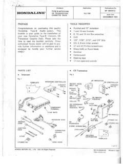
2 In situations where the whole switch may be submerged in water for long periods, it is recommended that the electrical housing be filled with an electrical grade (non acid curing) silicon sealant. There are no moving parts in the electrical enclosure of this switch so the entire housing can be simply potted in this way, if list for the F25 series Flow SwitchItemDescriptionQtyMaterial or Model1 Body1 Polypropylene2 Paddle C/W Magnet1 Polypropylene3 Sensitivity Cap1 Nylon4 Dust Cap1 Nylon5 Lid Gasket1 Santoprene6PC Board Spacer2 Polypropylene7 Cable Gland Nut1 ASA8 Backing Washer1 ASA9 Cable Grommet1 Santoprene10 Terminal Block1 Acetal11 Lid1 Polypropylene12Pc Board Screw2 Stainless Steel13 Lid Screw1304 Stainless Steel14 Screw Retainer1 Nitrile15 Nut1304 Stainless Steel16 Paddle Pivot Screw1 Polypropylene17 Circuit Board1FL25R, FL25B.
3 FL25C18 Reed Switch1 GlassGENERALIn the interest of safety, Do not use this switch in applications where the liquid temperature is greater than 60 C. OPERATING pressure (18 bars) must be de-rated linearity in direct proportion to temperature increase, to a maximum pressure of 1 bar absolute at 60 C. In other words only use this switch at elevated temperatures in non pressurised systems that are totally open to atmosphere in all circumstances and under all flow switch is intended to be installed in either horizontal or vertical pipework.
4 If the switch is to be used in vertical pipework, the flow of liquid in the pipe should be upward only. Never in a downward direction. There is some loss of sensitivity to flow when the flow switch arm lays in the horizontal plane, this is due to the weight of the paddle itself, and is particularly relevant in large pipes, OPERATING at low flows, where a full length paddle may be used. The switch may be installed in the suction or the discharge pipes of pumping systems. When bracket mounted, the switch may be used to detect flow in open channels. It will also function as an air flow switch in applications such as air conditioning ducting, due to its high sensitivity.
5 In horizontal pipework, the switch may be oriented at up to 60 either side of vertical. Under no circumstances should the flow switch be mounted on the underside of horizontal or angled pipework. Regardless of the orientation of the switch , it is important to ensure the paddle is exposed to a linear non turbulent flow of liquid. This is best achieved by mounting the switch in a straight run of pipe, of at least 5 pipe diameters both up and downstream of the switch . Never mount this switch close to valves or bends in the pipework, as both can cause turbulent flow.
6 The F25 flow switch is designed to be used in pipe systems ranging from 25mm (1 inch) upward. A 25mm BSP threaded socket must be provided, fixed at 9O to the axis of the pipe. For steel pipes of the larger sizes, a suitable socket may be welded to the main pipe. The most usual method however, for both steel and plastic pipe, is to use a reducing tee in the main pipe. The tee should have a 25mm BSP female thread to accept the flow switch . The F25 flow switch must be oriented in the flow stream so the liquid impinges on the paddle face, squarely.
7 There is an arrow on the side of the body of the flow switch which indicates the alignment of the switch in relation to the direction of flow through the pipe. The flow switch will not operate unless this orientation is F25 series flow switch has been specifically designed to be used in both water and aggressive chemical solutions. All wetted parts of the switch are made from thermo-plastics, which resist a wide range of chemicals such as acids, bases, sea water, ground water, and many solutions containing dissolved mineral salts. This switch should not be used in organic solvents.
8 There are no metal parts in the wetted area of this swich. The spring action of the paddle arm and the actuation of the switch is achieved solely by magnetic force, acting through the polypropylene walls of the switch . If there is any doubt as to the suitability of this flow switch to be exposed to specific chemicals, seek the advice of the manufacturer before INSTALLING this TRIMMINGWARNINGAll electrical work associated with the F25 series Paddle Flow switch must be carried out by qualified electrical personnel and all electrical work must conform to AS/NZ (or equivalent) standards and to local wiring rules.
9 The paddle of the F25 flow switch is intended to be cut off at a suitable length on each installation . Several factors should be considered when deciding how long the paddle should be. Firstly the F25 flow switch is an extremely sensitive device. It only takes a slight force against the paddle to actuate the switch . Liquid moving at reasonable velocity in a pipe will generate a considerable amount of force against the flow switch paddle. Any more load than is required to actuate the switch will only represent unnecessary stress, and possible premature failure of the paddle.
10 As a general recommendation, keep the paddle length as short as possible. Usually the paddle need not extend past the centre line of the pipe, and often even less paddle area exposed to the flow will suffice. In situations where the flow is known to be low, or in large pipes prone to partial draining, it may be necessary to use a longer paddle. If the paddle is inadvertently cut too short, this can, in many instances be compensated for by adjustment of the sensitivity screw located under the end of the electrical housing. Take care that the paddle is able to pivot freely through its full arc of motion, unencumbered.