Transcription of INSTALLING AND OPERATING THE KELCO F25 SERIES …
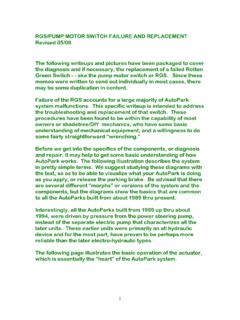
1 INSTALLING AND OPERATING THE KELCO F25 SERIES FLOW SWITCHENVIRONMENTWARNINGP lease read these installation and OPERATING instructions fully and carefully before INSTALLING or servicing this Paddle Flow switch . The F25 SERIES flow switch is mains voltage device. Death or serious injury may result if this switch is not correctly installed and operated. All electrical work must be performed by a fully qualified and licenced F25 SERIES flow switch has an IP rating of 56, that is, the unit is weather proof and may be used for all exposed outdoor applications. In situations where the whole switch may be submerged in water for long periods, it is recommended that the electrical housing be filled with an electrical grade (non acid curing) silicon sealant. There are no moving parts in the electrical enclosure of this switch so the entire housing can be simply potted in this way, if list for the F25 SERIES Flow SwitchItemDescriptionQtyMaterial or Model1 Body1 Polypropylene2 Paddle C/W Magnet1 Polypropylene3 Sensitivity Cap1 Nylon4 Dust Cap1 Nylon5 Lid Gasket1 Santoprene6PC Board Spacer2 Polypropylene7 Cable Gland Nut1 ASA8 Backing Washer1 ASA9 Cable Grommet1 Santoprene10 Terminal Block1 Acetal11 Lid1 Polypropylene12Pc Board Screw2 Stainless Steel13 Lid Screw1304 Stainless Steel14 Screw Retainer1 Nitrile15 Nut1304 Stainless Steel16 Paddle Pivot Screw1 Polypropylene17 Circuit Board1FL25R, FL25B, FL25C18 Reed Switch1 GlassGENERALIn the interest of safety, Do not use this switch in applications where the liquid temperature is greater than 60 C.
2 OPERATING pressure (18 bars) must be de-rated linearity in direct proportion to temperature increase, to a maximum pressure of 1 bar absolute at 60 C. In other words only use this switch at elevated temperatures in non pressurised systems that are totally open to atmosphere in all circumstances and under all flow switch is intended to be installed in either horizontal or vertical pipework. If the switch is to be used in vertical pipework, the flow of liquid in the pipe should be upward only. Never in a downward direction. There is some loss of sensitivity to flow when the flow switch arm lays in the horizontal plane, this is due to the weight of the paddle itself, and is particularly relevant in large pipes, OPERATING at low flows, where a full length paddle may be used. The switch may be installed in the suction or the discharge pipes of pumping systems. When bracket mounted, the switch may be used to detect flow in open channels.
3 It will also function as an air flow switch in applications such as air conditioning ducting, due to its high sensitivity. In horizontal pipework, the switch may be oriented at up to 60 either side of vertical. Under no circumstances should the flow switch be mounted on the underside of horizontal or angled pipework. Regardless of the orientation of the switch , it is important to ensure the paddle is exposed to a linear non turbulent flow of liquid. This is best achieved by mounting the switch in a straight run of pipe, of at least 5 pipe diameters both up and downstream of the switch . Never mount this switch close to valves or bends in the pipework, as both can cause turbulent flow. The F25 flow switch is designed to be used in pipe systems ranging from 25mm (1 inch) upward. A 25mm BSP threaded socket must be provided, fixed at 9O to the axis of the pipe. For steel pipes of the larger sizes, a suitable socket may be welded to the main pipe.
4 The most usual method however, for both steel and plastic pipe, is to use a reducing tee in the main pipe. The tee should have a 25mm BSP female thread to accept the flow switch . The F25 flow switch must be oriented in the flow stream so the liquid impinges on the paddle face, squarely. There is an arrow on the side of the body of the flow switch which indicates the alignment of the switch in relation to the direction of flow through the pipe. The flow switch will not operate unless this orientation is F25 SERIES flow switch has been specifically designed to be used in both water and aggressive chemical solutions. All wetted parts of the switch are made from thermo-plastics, which resist a wide range of chemicals such as acids, bases, sea water, ground water, and many solutions containing dissolved mineral salts. This switch should not be used in organic solvents. There are no metal parts in the wetted area of this swich.
5 The spring action of the paddle arm and the actuation of the switch is achieved solely by magnetic force, acting through the polypropylene walls of the switch . If there is any doubt as to the suitability of this flow switch to be exposed to specific chemicals, seek the advice of the manufacturer before INSTALLING this TRIMMINGWARNINGAll electrical work associated with the F25 SERIES Paddle Flow switch must be carried out by qualified electrical personnel and all electrical work must conform to AS/NZ (or equivalent) standards and to local wiring rules. The paddle of the F25 flow switch is intended to be cut off at a suitable length on each installation. Several factors should be considered when deciding how long the paddle should be. Firstly the F25 flow switch is an extremely sensitive device. It only takes a slight force against the paddle to actuate the switch .
6 Liquid moving at reasonable velocity in a pipe will generate a considerable amount of force against the flow switch paddle. Any more load than is required to actuate the switch will only represent unnecessary stress, and possible premature failure of the paddle. As a general recommendation, keep the paddle length as short as possible. Usually the paddle need not extend past the centre line of the pipe, and often even less paddle area exposed to the flow will suffice. In situations where the flow is known to be low, or in large pipes prone to partial draining, it may be necessary to use a longer paddle. If the paddle is inadvertently cut too short, this can, in many instances be compensated for by adjustment of the sensitivity screw located under the end of the electrical housing. Take care that the paddle is able to pivot freely through its full arc of motion, unencumbered. This is particularly relevant when the switch is mounted in an extension or stand off socket, for example in pipework which is to be lagged.
7 The paddle must be free to pivot fully back and forward, in order to actuate the switch INSTALLATIONThe switch lid is fitted with a cable gland sized to accept 10mm cable, or by removing the inner gland rubber, 6mm cable. If the cable gland nut is removed, the thread will accept a 20mm conduit bush. The switch should be connected in SERIES with the load. The terminals are marked S1, S2 and Earth. The switch is bidirectional so the active can be fed to either S1 or S2 and the switch wire to the load taken from the other available terminal, S1 or S2. The earth terminal is provided for safety, and should be used on every mains voltage installation. The F25 flow switch is available with 3 different circuit boards. The details of the electrical rating of each model can be found inside the lid of the electrical housing. Some additional details are included here: 1) F25-R (Circuit board is marked FL25R) Solid state relay, suited to control AC circuits between 2 and 250 volts.
8 This switch is suitable for all general purpose applications, for example, control of contactors and relays, or direct control of small motors. This switch will not operate in DC circuits, or in AC applications where the load is less than 10mA. To test the FL25R circuit board, use a 240 volt lamp connected in SERIES with the switch . Continuity testers and multimeters may yield false results if applied to the FL25R circuit board. The switch is supplied as a normally OFF switch which turns ON when flowing liquid moves the paddle. The terminal block, on the HAZARDOUS LOCATIONSThe F25 flow switch is classed as a simple device, it contains no mechanism for the storage or production of electrical energy. The switch does not require separate certification to be used in hazardous locations. The F25-B and F25-C switches are suited to hazardous area use, when isolated via an intrinsically safe relay (zener barrier).
9 There are two methods of setting the point at which the F25 flow switch operates, in relation to any given flow. By far the most effective is careful trimming of the paddle length. The second method should only be used to fine tune an installation. There is a sensitivity adjusting screw located at the upstream end of the switch under the end of the electrical housing. This is accessible by removing the hexagon headed plug, and adjustable using a broad bladed screwdriver. As supplied, the screw is wound fully in. This setting makes the switch least sensitive to liquid impinging on the paddle. The screw may be wound anticlockwise, to increase the sensitivity. That is, to make the switch respond to lower flows, or to a smaller area of paddle exposed to the flow. The screw should never be removed or wound out more than 6 full turns, and never wound in beyond its stop. The switch will not operate if the screw is ADJUSTMENTFull overhaul and service of the F25 flow switch may be carried out in the field, and in most instances without disturbing existing pipework.
10 Note that repairs should only be carried out by qualified electrical personnel. All components of the switch are available as spare parts, from the manufacturer, or supplier. See Fig 1 for a complete parts list for this AND REPAIRS circuit hoard, is toward the down stream end of the switch body. To convert the switch to a normally ON function, simply remove the 2 fixing screws and turn the circuit board end for end. Due to thermal dissipation factors, the amount of power the FL25R circuit board can control is limited to 750 Watts, continuous. If the continuous load is not limited to this rating, the triac temperature will become excessive (> 130 C) and the switch may lock in the ON state, until allowed to cool. 2) F25-B Single reed switch contact switch , suited to control of AC or DC circuits up to 25O volts at up to 40VA Principally intended for signalling of PLC s the F25-B can also be used as a light duty general purpose control switch .