Transcription of Instructables.com - RF 315/433 MHz Transmitter-receiver ...
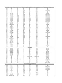
1 Living Outside Play Technology WorkshopRF 315/433 MHz Transmitter-receiver module and Arduinoby Mohannad Rawashdeh on October 3, 2013 Table of ContentsRF 315/433 MHz Transmitter-receiver module and arduino ..1 Intro: RF 315/433 MHz Transmitter-receiver module and arduino ..2 Step 1: module Specification ..3 Step 2: Schematics ..3 Step 3: arduino Virtual Wire Library ..4 Step 4: One transmitter , Multi receiver ..6 Step 5: Virtual Wire .. inside ..8 Related Instructables ..9 Advertisements ..9 Comments ..9 : RF 315/433 MHz Transmitter-receiver module and ArduinoHi every body , I searched on Instructables about a simple RF Transmitter-receiver module , Which is used in Remote control for cars , or to control simple tasks , likecontrol relay on/off unfortunately I didn't find What I need , So i decided to write a simple artical about this transceiver and How we can connect it with arduino andprogram it.
2 Materials: at first let's take a look for what we need :1) 2 arduino Board "I used Uno"2) RF 315 MHz or 433 mhz Transmitter-receiver module .3) jumper wire .4) BreadBoard .5)External Power supply (9V Battery *2) "Optional" . 1: module SpecificationThis module has a specification for : transmitter : Working voltage: 3V - 12V fo max. power use 12 VWorking current: max Less than 40mA max , and min 9mAResonance mode: (SAW)Modulation mode: ASKW orking frequency: Eve 315 MHz Or 433 MHzTransmission power: 25mW (315 MHz at 12V)Frequency error: +150kHz (max)Velocity : less than 10 KbpsSo this module will transmit up to 90m in open area . receiver :Working voltage: + current:? maxWorking method: OOK/ASKW orking frequency: : 2 MHzSensitivity: excel 100dBm (50?)Transmitting velocity: < (at 315 MHz and -95dBm)the use of an optional antenna will increase the effectiveness of your wireless communication.
3 A simple wire will do the Notes1. RF ReceiverImage Notes1. RF TransmitterStep 2: Schematicsthe connection for this module is very easy .for transmitter :Vcc >>>>5 VATAD>>>D12"You can change it as you like from Software" .Gnd >>> GndReceiver :Vcc>>>>5 VData>>>D12 Gnd>>> 3: arduino Virtual Wire LibraryFortunately , There is a popular Library for arduino Called "" VirtualWire"" Created by Mike McCauleyVirtualWire is an arduino library that provides features to send short messages, without addressing, retransmit or acknowledgment, a bit like UDP over wireless, usingASK (amplitude shift keying). Supports a number of inexpensive radio transmitters and library allow You to send and receive data"byte" and string easily ,First Download the library from Here .after extract the folder, and move it to " Libraries " on the arduino Folderthis is a simple code , it will send character '1' and after 2 sec will send character '0' and so on.
4 This code for transmitter ://simple Tx on pin D12//Written By : Mohannad Rawashdeh// 3:00pm , 13/6/2013// #include < >char *controller;void setup() {pinMode(13,OUTPUT);vw_set_ptt_inverted( true); //vw_set_tx_pin(12);vw_setup(4000);// speed of data transfer Kbps}void loop(){controller="1" ;vw_send((uint8_t *)controller, strlen(controller));vw_wait_tx(); // Wait until the whole message is gonedigitalWrite(13,1);delay(2000);contr oller="0" ;vw_send((uint8_t *)controller, strlen(controller));vw_wait_tx(); // Wait until the whole message is gonedigitalWrite(13,0);delay(2000);}and this is code for receiver :The D13 LED On the arduino board must be turned ON when received character '1' and Turned Off when received character '0'//simple Tx on pin D12//Written By : Mohannad Rawashdeh// 3:00pm , 13/6/2013// #include < >void setup(){ (true); // Required for DR3100vw_set_rx_pin(12);vw_setup(4000); // Bits per secpinMode(13, OUTPUT);vw_rx_start(); // Start the receiver PLL running}void loop(){uint8_t buf[VW_MAX_MESSAGE_LEN];uint8_t buflen = VW_MAX_MESSAGE_LEN;if (vw_get_message(buf, &buflen)) // Non-blocking{if(buf[0]=='1'){digitalWrit e(13,1);}if(buf[0]=='0'){digitalWrite(13 ,0);}}} 4: One transmitter , Multi ReceiverYou can connect many receiver and send a Data from One Master transmitter .
5 For more secret you may need Encoder-Decoder .Encoder is a circuit that changes a set of signals into a code .Decoder is a circuit that changes a code into a set of signals .if You need an Encoder/Decoder IC , You can use PT2262 and PT2272this is a simple example , for 1 master transmitter , 2 ReceiverS , and send a command through Serial for a receiver To Turn LED On/Off .Tx code ://simple Tx on pin D12//Written By : Mohannad Rawashdeh// 3:00pm , 13/6/2013// #include < >char *controller;void setup() {pinMode(13,OUTPUT);vw_set_ptt_inverted( true); //vw_set_tx_pin(12);vw_setup(4000);// speed of data transfer Kbps}void loop(){controller="A1" ;vw_send((uint8_t *)controller, strlen(controller));vw_wait_tx(); // Wait until the whole message is gonedigitalWrite(13,1);delay(1000);digit alWrite(13,0);delay(1000);controller="B1 " ;vw_send((uint8_t *)controller, strlen(controller));vw_wait_tx(); // Wait until the whole message is gonedigitalWrite(13,1);delay(1000);digit alWrite(13,0);delay(1000);}First Rx//simple Tx on pin D12//Written By : Mohannad Rawashdeh// 3:00pm , 13/6/2013// #include < >void setup(){vw_set_ptt_inverted(true); // Required for DR3100vw_set_rx_pin(12).}
6 Vw_setup(4000); // Bits per secpinMode(13, OUTPUT);vw_rx_start(); // Start the receiver PLL running}void loop(){uint8_t buf[VW_MAX_MESSAGE_LEN];uint8_t buflen = VW_MAX_MESSAGE_LEN;if (vw_get_message(buf, &buflen)) // Non-blocking{if((buf[0]=='A')&&(buf[1]== '1')){digitalWrite(13,1);delay(1000);}}e lse{digitalWrite(13,0);}} Rx//simple Tx on pin D12//Written By : Mohannad Rawashdeh// 3:00pm , 13/6/2013// #include < >void setup(){vw_set_ptt_inverted(true); // Required for DR3100vw_set_rx_pin(12);vw_setup(4000); // Bits per secpinMode(13, OUTPUT);vw_rx_start(); // Start the receiver PLL running}void loop(){uint8_t buf[VW_MAX_MESSAGE_LEN];uint8_t buflen = VW_MAX_MESSAGE_LEN;if (vw_get_message(buf, &buflen)) // Non-blocking{if((buf[0]=='B')&&(buf[1]== '1')){digitalWrite(13,1);delay(1000);}}e lse{digitalWrite(13,0);}} 5: Virtual Wire.
7 InsideVirtualWire is an arduino library that provides features to send short messages, without addressing, retransmit or acknowledgment, a bit like UDP over wireless, usingASK (amplitude shift keying). Supports a number of inexpensive radio transmitters and are sent with a training preamble, message length and checksum. Messages are sent with 4-to-6 bit encoding for good DC balance, and a CRC checksum formessage we use Serial communication with ? answer is NoASK receivers require a burst of training pulses to synchronize the transmitter and receiver , and also requires good balance between 0s and 1s in the message stream inorder to maintain the DC balance of the message, UARTs do not provide these. They work a bit with ASK wireless, but not as well as this full function for this library :To use the VirtualWire library, you must have#include < >To select the transmitter Data Pin , void :vw_set_tx_pinTo select the receiver Data Pin , void :vw_set_rx_pinSetup the speed of transmission , The speed of Tx must be as same as On Rx.
8 The speed will be a Number of Bit Per Second between 0-9600 , for short distance you can use fast speed , For long distance "Up to 90m" you must use lowertransmission speed as much as possible .vw_setup(uint16_t speed);Start the receiver PLL running ,You must do this before you can receive any messages,Callvw_rx_start(); must do this before you can receive any messages. When a messageis available (good checksum or not), vw_have_message() will return ();Block and wait until the transmitter is idle,called :vw_wait_tx();Block and wait until a message is available from the receiver , call :vw_wait_rx();Send a message with the given length, call :vw_send(uint8_t* buf, uint8_t len);Returns true if an unread message is available from the receiver .,call :vw_have_message();Related InstructablesModulos RF433 Mhz conArduino byDaniel ArturoFWireless indoor& outdoorthermometer byMisloElectronicsWireless PIRS ensor Alarm byMisloElectronicsMake yourArduino projectwireless inminutes, withthe WirelessInventors Shield(video) byopensourcerfWirelesscommunicationArdui no RF byEagle199393 ArduinoWireless SDShield Tutorialby randofoAdvertisementsComments50 commentsAdd Commentview all 110 comments says: Dec 23, 2014.
9 8:51 AM REPLYHi! Can I use the transmitter module with a VCC of 12 V and connect the data directly to the arduino D12? moon_toon101 says: Dec 30, 2014. 11:49 AM REPLYK alium can you help me in a project? Will pay for spudziuvelis says: Dec 18, 2014. 6:58 AM REPLYA rduino: (Windows 8), Board: " arduino Mega or Mega 2560, ATmega2560 (Mega 2560)"In file included from :6:0:C:\Program Files (x86)\ arduino \libraries\ :14:20: fatal error: : No such file or directory#include^compilation report would have more information with"Show verbose output during compilation"enabled in File > was trying to compile trasmitter example aaaaand this error says: Dec 23, 2014. 4:36 AM REPLYYou must install the VirtualWire library before compile the code, you can download it from the article where it says: "First Download the library from Here.
10 ". Afterwards, uncompress it to your arduino library folder which is in this case: "C:\Program Files (x86)\ arduino \libraries\"After doing this, close all arduino compiler interfaces and you should see a new set of examples. The code is now able to run. Good luck ;). spudziuvelis says: Dec 23, 2014. 5:57 AM REPLYI installed the library but it doesn't matter now cause i fixed it myself by downgrading from Ide to and it worked gabrielaugustin84 says: Oct 28, 2014. 3:17 PM REPLYhi there!!!!!how do i add multiple switch to transmitter and the receiver is connected to a simple numeric display where it will show which switch is switched in order? robobot3112 says: Dec 11, 2014. 7:57 AM REPLY//code for the tx#include < >//Assigning controller buttons to Digital Pinsint s5 = 8;int s4 = 9;int s3 = 10;int s2 = 11;int s1 = 12;int remotePins[]= {8,9,10,11,12};//array to store pin nosvoid setup(){ (9600); // Debugging ("setup");// Initialise the IO and ISRvw_setup(2000); // Bits per secvw_set_tx_pin(3); // transmitter Data Pin to Digital Pin 3for(int i = 0; i<6 ; i++){pinMode(remotePins[i], INPUT);digitalWrite(remotePins[i],HIGH); }/*This is what the loop above does :-pinMode(8, INPUT);pinMode(9, INPUT);pinMode(10, INPUT);pinMode(11, INPUT);pinMode(12, INPUT);digitalWrite(8, HIGH);digitalWrite(9, HIGH);digitalWrite(10, HIGH);digitalWrite(11, HIGH);digitalWrite(12, HIGH);*/pinMode(groundpin, OUTPUT);pinMode (powerpin,OUTPUT);digitalWrite(powerpin, HIGH).}