Transcription of Instruction Manual: Fisher 3660 and 3661 Positioners
1 3660 and 3661 of Area Classifications and SpecialInstructions for Safe Use and Installationin Hazardous Locations for 3661 on 1250, 1250R, 3024 Sand GX on Baumann on 657 and 667 Actuators,Size 30i through on 657 and 667 ActuatorsSize 30 through Lever Assembly andRange Spring Connections for 3661 Range Bypass of the positioner the Range the Input Signal Range on3660 the positioner from the Bolt Mounting on 1250, 1250R,3024S and Baumann Mounting on 1250, 1250 Rand 3024S Bracket/U Bolt Mounting on657 and 667 the Input ModuleDiaphragm 1. Fisher 3660 positioner Mounted on a Baumann ActuatorW7174 Disassembling and Assembling and Assembling the the 3661 Converter Common ManualD101402X0123660 and 3661 PositionersOctober 2018 Instruction ManualD101402X0123660 and 3661 PositionersOctober 20182 IntroductionScope of ManualThis Instruction manual includes installation, operation, calibration, maintenance, and parts ordering information forFisher 3660 and 3661 positioners .
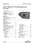
2 Refer to separate Instruction manuals for information on the actuator and not install, operate, or maintain a 3660 or 3661 positioner without being fully trained and qualified in valve,actuator and accessory installation, operation and maintenance. To avoid personal injury or property damage it isimportant to carefully read, understand, and follow all of the contents of this manual , including all safety cautions andwarnings. If you have any questions about these instructions , contact your Emerson sales office before pneumatic and 3661 electro pneumatic, single acting Positioners are used with Fisher 657, 667, 1250, 1250R,3024S, and GX actuators. These Positioners can also be mounted on Baumann actuators. Figure 1 shows a 3660positioner mounted on a Baumann positioner mounts on the actuator and provides the desired plug position for a specific input signal. The 3660positioner accepts a pneumatic signal and the 3661 accepts a 4 to 20 milliampere DC input for the 3660 and 3661 positioners are shown in table ServicesFor information on available courses for 3660 and 3661 positioners , as well as a variety of other products, contact:Emerson Automation SolutionsEducational Services, RegistrationPhone: +1-641-754-3771 or +1-800-338-8158e mail: ManualD101402X0123660 and 3661 PositionersOctober 20183 Table 1.
3 SpecificationsAvailable ConfigurationThe Fisher 3660 series of Positioners include thefollowing models:3660: Single acting pneumatic valve positioner3661: Single acting electro pneumatic valvepositionerInput to bar (3 to 15 psig), to bar (6 to 30 psig), orJsplit range (see tables 3 and 4)3661:J 4 to 20 mA DC constant current with 30 VDCmaximum compliance range is also available, see tables 3 and 4 Equivalent Circuit (3661)120 ohms shunted by three V zener diodesOutput SignalType: Pneumatic pressure as required by the actuatorup to full supply pressureAction:JDirect (increasing input signal pressure increasespositioner output),JReverse (increasing input signal pressuredecreases positioner output)Supply Pressure(1)Recommended: 10% above actuator requirementsMaximum: bar (90 psig) or pressure rating ofactuator, whichever is lowerMedium: Air3660 and 3661 are not compatible with natural gasas the supply mediumPerformanceIndependent Linearity: 1% of output spanHysteresis: of output span(2)Deadband: of input spanElectromagnetic Compatibility for 3661electro pneumatic positioner :Meets EN 61326 1:2013 Immunity Industrial locations per Table 2 of the EN 61326 1 standard.
4 Performance is shown in table 2 Class A ISM equipment rating: Group 1, Class APositioner AdjustmentsSpan: JAdjustable up to 20 mm ( inch) stemtravel, or J Adjustable from 20 mm ( inch) to 50mm (2 inch) stem travelZero: 0 to 100%Gain: to 6% PB (proportional band)(3)Output Volume Damping: Loop dynamic responseadjustmentDelivery Capacity(4) Bar (20 Psig) Supply: normal m3/hour (150 scfh) Bar (35 Psig) Supply: normal m3/hour(230 scfh)Exhaust Capacity(4) Bar (20 Psig) Supply: normal m3/hour(170 scfh) Bar (35 Psig) Supply: normal m3/hour(260 scfh)Steady State Air Consumption(4,5)3660: normal m3/hour ( scfh) at bar (20 psig) supply pressure. normal m3/hour ( scfh) at bar (35 psig) supply pressure3661: normal m3/hour ( scfh) at bar (20 psig) supply pressure. normal m3/hour ( scfh) at bar (35 psig) supply pressureOperating InfluenceSupply Pressure: 70 mbar (1 psig) change in supplypressure changes the actuator stem position less (6) of travelOperative Temperature Limits(1)-40 to 82 C (-40 to 180 F)Hazardous Area Classification for 36603660 pneumatic Positioners comply with therequirements of ATEX Group II Category 2 Gas andDust- continued - Instruction ManualD101402X0123660 and 3661 PositionersOctober 20184 Table 1.
5 Specifications (Continued)Hazardous Area Classification for 3661 CSA & FM Intrinsically Safe, Type n, Non incendiveATEX & IECEx Intrinsically Safe, Type n (Gas Atmospheres Only)Housing Classification for 3661 CSA Type 3 NEMA 3, IP54 ATEX & IECEx IP44 Mounting orientation requires vent location to bebelow Classifications/Certifications for 3661 CUTR Customs Union Technical Regulations (Russia,Kazakhstan, Belarus, and Armenia)INMETRO National Institute of Metrology, Quality,and Technology (Brazil)KGS Korea Gas Safety Corporation (South Korea)Contact your Emerson sales office forclassification/certification specific informationMountingThe positioner can be mounted in one of fourdifferent configurations. See figure 2 for Connections1/4 NPT internalConduit Connection for 36611/2 NPT (M20 or PG13 adaptors, optional)Maximum Valve Stem TravelTwo ranges:J50 mm (2 inch) to 20 mm ( inch) minimum;J20 mm ( inch) adjustable to lesser travel withstandard input signalApproximate Weight3660: kg ( pounds)3661: kg ( pounds)Vent Connection1/4 NPT internalOptions3660: JInstrument and output pressure gauges,JIntegrally mounted bypass valve3661: Output pressure gaugeDeclaration of SEPF isher Controls International LLC declares thisproduct to be in compliance with Article 4 paragraph3 of the PED Directive 2014/68/EU.
6 It was designedand manufactured in accordance with SoundEngineering Practice (SEP) and cannot bear the CEmarking related to PED , the product may bear the CE marking toindicate compliance with other applicable EuropeanCommunity : Specialized instrument terms are defined in ANSI/ISA Standard - Process Instrument The pressure/temperature limits in this manual and any applicable standard or code limitation should not be Hysteresis value at a gain setting of 1/2 Adjusting the gain (PB) adjustment changes the nozzle flapper relationship. This nozzle flapper change affects the actuator/ positioner response Normal m3/hr normal cubic meters per hour (0 C and bar absolute); Scfh standard cubic feet per hour (60 F and psia). 5. Air consumption at a gain setting of 1/2 At supply pressure of bar (35 psig).Table 2. Fisher 3661 positioner EMC Summary Results ImmunityPortPhenomenonBasic StandardTest LevelPerformanceCriteria(1)EnclosureElec trostatic discharge (ESD)IEC 61000 4 24 kV contact8 kV airARadiated EM fieldIEC 61000 4 380 to 1000 MHz @ 10V/m with 1 kHz AM at 80%1400 to 2000 MHz @ 3V/m with 1 kHz AM at 80%2000 to 2700 MHz @ 1V/m with 1 kHz AM at 80%ARated power frequency magnetic fieldIEC 61000 4 860 A/m at 50 HzAI/Osignal/controlBurstIEC 61000 4 41 kVASurgeIEC 61000 4 51 kV (line to ground only, each)BConducted RFIEC 61000 4 6150 kHz to 80 MHz at 3 VrmsASpecification limit = 1% of span1.
7 A = No degradation during testing. B = Temporary degradation during testing, but is self ManualD101402X0123660 and 3661 PositionersOctober 20185 InstallationTypically, a positioner is shipped with the actuator. If so, the factory mounts and calibrates the positioner and connectsthe positioner to actuator tubing. If the positioner is ordered separately from the actuator, perform the appropriatemounting procedure. Refer to the appropriate Instruction manuals for actuator and valve installation procedures. WARNINGA lways wear protective clothing, gloves, and eyewear when performing any Installation procedures to avoid installing into an existing application, also refer to the WARNING at the beginning of the Maintenance section in thisinstruction with your process or safety engineer for any additional measures that must be taken to protect against not use sealing tape on pneumatic connections. This instrument contains small passages that may become obstructedby detached sealing tape.
8 Thread sealant paste should be used to seal and lubricate pneumatic threaded Area Classifications and Special instructions for Safe Use andInstallation in Hazardous Locations for 3661 PositionerRefer to the following Instruction manual supplements for approval CSA Hazardous Area Approvals, Fisher 3661 positioner (D104228X012)D FM Hazardous Area Approvals, Fisher 3661 positioner (D104229X012)D ATEX Hazardous Area Approvals, Fisher 3661 positioner (D104230X012)D IECEx Hazardous Area Approvals, Fisher 3661 positioner (D104231X012)Documents are available from your Emerson sales office or Contact your Emerson sales office for all otherapproval/certification ManualD101402X0123660 and 3661 PositionersOctober 20186 positioner MountingMounting on 1250, 1250R, 3024S, and GX ActuatorsDuring the following mounting procedures, refer to figures 3, 26, and 27 for key number 3 shows keys 64 through 78 and 101 through 104. Other key numbers are shown in either figure 26 for the3660 positioner or figure 27 for the 3661 positioner .
9 Two mounting methods are available, center bolt mounting andclamp Determine the positioner mounting configuration from figure 2. The actuator size, actuator travel, and positioneraction must be known. If center bolt mounting is desired, be certain the actuator is equipped with tapped holes inthe Thread the hex head screws with washers (keys 69 and 70) several turns into the stem connector. The feedbackplate (key 68) is reversible and must be positioned so that the pilot shaft (key 19A) will operate correctly in the slotof the feedback plate. For actuator travels between 20 and 30 mm ( and inches) (for 3024S actuators,travel ranges between 16 and 32 mm), position the feedback plate so the long portion of its slot, when bolted tothe stem connector, is closest to the positioner as shown in figure 4. For travels greater than 30 mm ( inches),reverse the position of the feedback plate as shown in figure For size 30 and 34 actuators with all travels and for size 45 actuators with travel greater than 30 mm ( ), position the feedback plate (key 68) between the stem connector and washers and tighten the hex headscrews (key 69).
10 B. For size 45 actuators with travel between 20 and 30 mm ( and inches) (16 and 32 mm for 3024 Sactuators), attach the feedback adaptor (key 103) to the feedback plate (key 68) using machine screws,lockwashers, and wedge nuts (keys 102, 101, and 104). The feedback plate and the wedge nuts must beassembled as shown in the lower right portion of figure 3. Use the mounting holes in the feedback adaptor andposition it as indicated in figure 4. Then, position the feedback plate between the stem connector and washersand tighten the hex head screws (key 69).3. Unscrew the two machine screws (key 24), and remove the positioner cover (key 21).Center Bolt Mounting (GX Actuator)a. As shown in figure 5, a thin knockout section is cast across the mounting hole in the housing. Check to makecertain this knockout section has been removed. If the knockout section has not been removed, use a punch toknock it Attach the positioner to the actuator using a sealing washer and hex head screw (keys 71 and 72).