Transcription of Instruction Manual: Fisher ES and EAS easy-e Valves …
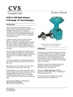
1 ES and EAS easy e ValvesCL125 through of Metal Plug SEAL Bellows Seal and a Plain or Extension Bonnet with anENVIRO SEAL Bellows Seal (Stem/BellowsAssembly) and of an Installed ENVIRO SEALB ellows Seal (Stem/Bellows Assembly) the ENVIRO SEAL BellowsSeal 1. Fisher ES Valve with 657 ActuatorW2174 3 IntroductionScope of ManualThis Instruction manual includes installation, maintenance, and parts information for NPS 1/2 through 8 Fisher ESvalves, and NPS 1 through 6 EAS Valves , through cl600 ratings. Refer to separate manuals for instructions covering theactuator and not install, operate, or maintain an ES valve without being fully trained and qualified in valve, actuator, andaccessory installation, operation, and maintenance. To avoid personal injury or property damage, it is important tocarefully read, understand, and follow all the contents of this manual, including all safety cautions and warnings. If youhave any questions about these instructions, contact your Emerson sales office or Local Business Partner ManualD100397X012ES ValveNovember 2017 Instruction ManualD100397X012ES ValveNovember 20172 Table 1.
2 SpecificationsEnd Connection StylesCast Iron ValvesFlanged: cl125 flat face or CL250 raised face flangesper ASME and Stainless Steel ValvesFlanged: CL150, 300, and 600 raised face or ring typejoint flanges per ASME or Socket Welding: All available ASME that are consistent with cl600 per : Consistent with ASME Inlet Pressure(1)Cast Iron ValvesFlanged: Consistent with CL125B or 250 Bpressure temperature ratings per ASME and Stainless Steel ValvesFlanged: Consistent with CL150, 300, and 600(2)pressure temperature ratings per ASME or Welding: Consistent with CL600pressure temperature ratings per ASME ClassificationsSee table 2 Flow CharacteristicsStandard Cages: Linear, quick opening, or equalpercentageWhisper Trim and WhisperFlo Cages: LinearFlow DirectionsStandard Cages: Normally upWhisper Trim and WhisperFlo Cages: Always upApproximate WeightsVALVE SIZE, NPSWEIGHTkgPounds1/2 and 3/41 and 1 1/41 1/222 1/23468111420394554774594082530456710012 51703509001. The pressure/temperature limits in this manual and any applicable standard or code limitation for the valve should not be Certain bonnet bolting material selections may require a cl600 easy e valve assembly to be derated.
3 Contact your Emerson sales office or Local Business single port Valves have cage guiding, quick change trim, and unbalanced push down to close valve plug configurations are as follows:ES Globe style valve (figure 1) with metal to metal seating as standard for all general applications over a wide rangeof pressure drops and temperatures, and metal to PTFE seating is optional for more stringent shutoff Angle valve version of ES, used to facilitate piping or in applications where a self draining valve body is specifications for these Valves are shown in table WARNINGA lways wear protective gloves, clothing, and eyewear when performing any installation operations to avoid injury or equipment damage caused by sudden release of pressure may result if the valve assembly is installedwhere service conditions could exceed the limits given in table 1 or on the appropriate nameplates. To avoid such injury ordamage, provide a relief valve for over pressure protection as required by government or accepted industry codes andgood engineering ManualD100397X012ES ValveNovember 20173 Check with your process or safety engineer for any additional measures that must be taken to protect against installing into an existing application, also refer to the WARNING at the beginning of the Maintenance section in thisinstruction 2.
4 Available Shutoff Classifications per ANSI/FCI 70 2 and IEC 60534 4 SeatingShutoff ClassMetalIV (standard)VPTFEVICAUTIONWhen ordered, the valve configuration and construction materials were selected to meet particular pressure, temperature,pressure drop, and controlled fluid conditions. Since some body/trim material combinations are limited in their pressuredrop and temperature ranges, do not apply any other conditions to the valve without first contacting your Emerson salesoffice or Local Business installing the valve, inspect the valve and pipelines for any damage and any foreign material which may causeproduct Before installing the valve, inspect the valve and associated equipment for any damage and any foreign Make certain the valve body interior is clean, that pipelines are free of foreign material, and that the valve isoriented so that pipeline flow is in the same direction as the arrow on the side of the The control valve assembly may be installed in any orientation unless limited by seismic criteria.
5 However, thenormal method is with the actuator vertical above the valve. Other positions may result in uneven valve plug andcage wear, and improper operation. With some Valves , the actuator may also need to be supported when it is notvertical. For more information, consult your Emerson sales office or Local Business Use accepted piping and welding practices when installing the valve in the line. Internal elastomeric parts may stayin place during the welding procedure. For flanged Valves , use a suitable gasket between the valve and on valve body materials used, post weld heat treating may be required. If so, damage to internal elastomericand plastic parts, as well as internal metal parts is possible. Shrunk fit pieces and threaded connections may also loosen. Ingeneral, if post weld heat treating is to be performed, all trim parts should be removed. Contact your Emerson sales officeor Local Business Partner for additional With a leak off bonnet construction, remove the pipe plugs (keys 14 and 16, figure 8) to hook up the leak offpiping.
6 If continuous operation is required during inspection or maintenance, install a three valve bypass aroundthe control valve If the actuator and valve are shipped separately, refer to the actuator mounting procedure in the appropriateactuator Instruction manual. WARNINGP ersonal injury could result from packing leakage. Valve packing was tightened before shipment; however, the packingmight require some readjustment to meet specific service ManualD100397X012ES ValveNovember 20174 Valves with ENVIRO SEAL live loaded packing or HIGH SEAL Heavy Duty live loaded packing will not require this initialre adjustment. See the Fisher Instruction manuals titled ENVIRO SEAL Packing System for Sliding Stem Valves orHeavy Duty Live Loaded Packing System (as appropriate) for packing instructions. If you wish to convert your presentpacking arrangement to ENVIRO SEAL packing, refer to the retrofit kits listed in the Parts Kits sub section near the endof this parts are subject to normal wear and must be inspected and replaced as necessary.
7 Inspection and maintenancefrequency depends on the severity of service conditions. This section includes instructions for packing lubrication,packing maintenance, trim maintenance, and ENVIRO SEAL bellows seal replacement. All maintenance operationsmay be performed with the valve in the line. WARNINGA void personal injury or damage to property from sudden release of pressure or uncontrolled process fluid. Before startingdisassembly:D Do not remove the actuator from the valve while the valve is still Always wear protective gloves, clothing, and eyewear when performing any maintenance operations to avoid Disconnect any operating lines providing air pressure, electric power, or a control signal to the actuator. Be sure theactuator cannot suddenly open the Use bypass Valves or completely shut off the process to isolate the valve from process pressure. Relieve process pressureon both sides of the valve. Drain the process media from both sides of the Vent the power actuator loading pressure and relieve any actuator spring Use lock out procedures to be sure that the above measures stay in effect while you work on the The valve packing box may contain process fluids that are pressurized, even when the valve has been removed from thepipeline.
8 Process fluids may spray out under pressure when removing the packing hardware or packing rings, or whenloosening the packing box pipe Check with your process or safety engineer for any additional measures that must be taken to protect against instructions carefully to avoid damaging the product surfaces, which could result in damage to the a gasket seal is disturbed by removing or shifting gasketed parts, a new gasket should be installed upon is necessary to ensure a good gasket seal since the used gasket may not seal the valve has ENVIRO SEAL or HIGH SEAL live loaded packing installed, refer to Instruction manuals ENVIRO SEAL PackingSystem for Sliding Stem Valves , D101642X012, or HIGH SEAL Live Loaded Packing System (D101453X012), for packingInstruction ManualD100397X012ES ValveNovember 20175instructions. Figure 9 shows a typical HIGH SEAL Packing system. Figures 10, 11, and 12 show typical ENVIRO SEAL the valve has an ENVIRO SEAL bellows seal bonnet installed, refer to this manual.
9 See the ENVIRO SEAL Bellows Seal and Bonnetsection for information on the bellows seal 2. Optional Lubricator and Lubricator/Isolating ValveLUBRICATORLUBRICATOR/ISOLATING VALVE10A9421 AAJ5428 DA0832 2 Table 3. Body to Bonnet Bolt Torque GuidelinesVALVE SIZE, NPSBOLT TORQUES(1, 4)ESEASSA193 B7, SA193 B8M(3)SA193 B8M(2)NSmLbfSftNSmLbfSft1 1/4 or less11299564471 1/2, 1 1/2 x 1, 2, or 2 x 12 or 2 x 1967145332 1/2 or 2 1/2 x 1 1/23 or 3 x 1 1/21299564473, 3 x 2, or 3 x 2 1/24 or 4 x 216912588654, 4 x 2 1/2, or 4 x 36 or 6 x 2 1/22712001561156 5494053662708 7465505293901. Determined from laboratory SA193 B8M SA193 B8M strain For other materials, contact your Emerson sales office or Local Business Partner for LubricationNoteENVIRO SEAL or HIGH SEAL packing does not require lubrication. WARNINGTo avoid personal injury or property damage resulting from fire or explosion, do not lubricate packing used in oxygenservice or in processes with temperatures over 260_C (500_F).
10 If a lubricator or lubricator/isolating valve (figure 2) is provided for PTFE/composition or other packings that requirelubrication, it will be installed in place of the pipe plug (key 14, figure 8). Use a good quality silicon base used in oxygen service or in processes with temperatures over 260_C (500_F) should not be lubricated. Tooperate the lubricator, simply turn the cap screw clockwise to force the lubricant into the packing box. Thelubricator/isolating valve operates the same way except the isolating valve must first be opened and then closed afterlubrication is ManualD100397X012ES ValveNovember 20176 Packing MaintenanceKey numbers refer to figure 3 for PTFE V ring packing and to figure 5 for PTFE/composition packing, unless spring loaded single PTFE V ring packing, the spring (key 8, figure 3) maintains a sealing force on the packing. Ifleakage is noted around the packing follower (key 13, figure 3), check to be sure the shoulder on the packing followeris touching the bonnet.