Transcription of Instruction Manual for Installing HIGH-STRENGTH …
1 Instruction Manualfor InstallingHIGH-STRENGTHBOLTS withDIRECTTENSION INDICATORS(ASTM F959M)METRIC SERIES EDITIONT urnaSure LLC 2011 TurnaSure LLC. All Rights OF CONTENTSI ntroduction .. 1 Theory of HIGH-STRENGTH Tension Indicators (DTIs) .. 3 bolt Tensioning Using Plain Finish DTIs .. 6 bolt Tensioning Using Coated DTIs .. 9 Recommended bolt Installation 12 Problems Commonly Encountered WhenTensioning Bolts .. 14 Tool Selection and Performance .. 16 Checking for Specification Conformance .. 17 DTI Identification Markings .. 20 Installation instructions for Bridge Applicationsper AASHTO ..Inside Back CoverTurnaSure LLC9th Ed. June 2008 International HeadquartersPhone: 215-750-1300 Fax: 215-750-6300340 E. Maple Ave., Suite 206800-525-7193 Email: PA 19047 Website: 2011 TurnaSure LLC. All Rights bolts are well established as economical and effi-cient devices for connecting structural steel.
2 When North Americandesign and construction practices are followed, theSpecification forStructural Joints Using ASTM A325 or A490 Bolts, Approved by theResearch Council on Structural Connections, sets the basic rules fortheir use. Designers and inspectors should be thoroughly familiarwith this Tension Indicators (DTIs) are recognized by many engi-neers as the most reliable method for ensuring correct installation ofhigh- strength bolts according to that specification for bothshear/bearing connections and connections requiring fully preten-sioned bolts. This Manual is written for engineers, construction superin-tendents, inspectors and iron workers to assist them in the properinstallation of HIGH-STRENGTH bolts using DTIs. This will ensure thatbolts have been tensioned to the values required whether used inslip-critical connections, connections subjected to direct tension, orshear/bearing connections requiring fully pretensioned bolts.
3 Theseinstructions are also valid when DTIs are specified for use with highstrength bolts in other connections as a device to ensure that all boltshave actually been handbook discusses the theory of slip-critical connectionsor connections subjected to direct tension, proper installation ofDTIs, general rules for bolt installation, problems typically encoun-tered when Installing HIGH-STRENGTH bolts and many other subjects rel-ative to HIGH-STRENGTH LLC has years of HIGH-STRENGTH bolting experienceand provides a range of consultation activity including seminars, sitevisits, tool recommendations, specification commentary and trainingprograms. In addition TurnaSure LLC prepares instructional DVDs,published technical reports and articles for publication in trade jour-nals. Should you wish to receive any of this information or be placedon our mailing list, please contact us at the address shown on theinside inch series edition of this Manual is available upon request,or you can print the PDF version available on our web site.
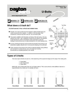
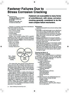
4 2011 TurnaSure LLC. All Rights OOFF HHIIGGHH SSTTRREENNGGTTHH BBOOLLTTIINNGGThe principle of slip-critical connections relies upon tensioningeach bolt in the connection to a specified minimum tension so thatthe desired clamping force will be induced in the connection inter-face. Shear loads are then transferred by frictional resistance in thejoint interface rather than by bearing on the bolt shanks and holefaces. In this type of connection there will be no movement of theconnected materials when the connection is subjected to theseloads. Movement in many types of joints is highly undesirable, hencethe development of the slip-critical connection. (Figure 1)FFiigguurree 11 When tension loads are applied in the direction of the bolt axis,tensioning to a specified minimum tension is also important, particu-larly if the loads are cyclical and could induce loosening or fatiguefailure of the bolts.
5 The clamping force at the specified minimum ten-sion should be greater than the applied loads. This will prevent theplies from separating or the bolts from developing any significantincrease in tension stress over the installed pretension stress.(Figure 2)FFiigguurree 22 2011 TurnaSure LLC. All Rights TTEENNSSIIOONN IINNDDIICCAATTOORRSS ((DDTTIIss))Direct Tension Indicators (DTIs) are simple and extremely accu-rate devices for ensuring that bolts have been installed above thespecified minimum tension value. Used properly they positivelyeennssuurree tthhee ccoorrrreecctt aammoouunntt ooff ccllaammppiinngg RReeaaddeerrss wwhhoohhaavvee iinnssttaalllleedd hhiigghh--ssttrreennggtthh bboollttss uussiinngg ttoorrqquuee//tteennssiioonn vvaalluueesswwiillll nnoottiiccee tthhaatt tthhiiss mmaannuuaall ddooeess nnoott rreellaattee ttoorrqquuee ttoo , , oorr ttwwiisst tiinngg ffoorrccee, , iiss nnoott aa rreel liiaabbllee mme eaassuurree ooff bboolltt DDTTIIss mme eaassuurree tteennssiioonn rreeggaarrddlleessss ooff aapppplliieedd is a hardened, washer-shaped device with protrusions, bumps, pressed out on one face, manufactured according to theprovisions of ASTM F959M.
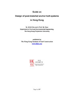
6 The fact that it resembles a washer isincidental. It is, in fact, a precision made mechanical load cell, adevice for tensioning which is covered by an ASTM a DTI is installed on a bolt with the bumps placedagainst the underside of the bolt head there are noticeable gapsbetween the bumps. As the nut is turned and the bolt tensioned, the bumps flatten. When the bumps are flattened so that the gapshave been reduced to the required dimension, the bolt has beenproperly tensioned and required clamping force is present. A DTIdoes not make it more difficult to tension a bolt , it merely shows thatthe bolt has been properly tensioned. (Figure 3)FFiigguurree 33 Direct Tension Indicators are supplied either plain finish, thatis without a coating, mechanically galvanized to ASTM B695 Class 50,or produced from weathering steel for use with Type 3 high -strengthbolts.
7 Other coatings may be available upon 2011 TurnaSure LLC. All Rights otherwise specified, uncoated DTIs are installed underthe bolt head and the nut turned. When the bolt is properly tensionedthe gap will be less than in more than half of the DTIs are installed using a criteria. To assure thatthe DTI is properly installed, feeler gages, and , are provided with DTI shipments. To ensure that the DTI isproperly compressed, and the bolt tensioned, the appropriate feelergage must be refused in a given number of gaps between the bumps. (Table I lists the number of bumps for each size and gradeof DTI and the required number of gage refusals in the gaps.)TTaabbllee 11 Should the specifications or conditions of installation call for anaverage gap of lessthan the feeler gage must be refusedin all 44 When inserted the feeler gage must be pointed at the center ofthe bolt and be at the center of the space.
8 Notches in the ofthe DTI assist in feeler gage inspection. (Figure 4).BBoollttTTYYPPEE *4343M164343M205364M225364M246474M276474 M307485M368595*Not currently in ASTM for bolts or DTIsM-22 mm 2011 TurnaSure LLC. All Rights , installation crews develop a feel for installation andcan install DTIs to the correct gap by eye. Inspectors will want to ver-ify that the correct gap has been achieved using a feeler gage on alimited number of DTIs and then compare other gaps by ccoommpprreesssseedd DDTTIIss sshhoouulldd nnoott bbee judge that a bolt which has fully compressed a DTI is overtensioned. No specific definition of overtensioned exists inbolt literature. Many experts believe that unless a tensioned bolt hasbroken it is acceptable. Further support for this recommendation canbe found in a report published in Volume 36, No.
9 1 of theEngineeringJournal, The Effects of Over-Compressing ASTM F959 DirectTension indicators on A325 Bolts Used in Shear Connections. RREEUUSSEE OOFF DDIIRREECCTT TTEENNSSIIOONN IINNDDIICCAATTOORRSS OONN HHIIGGHH SSTTRREENNGGTTHH SSTTRRUUCCTTUURRAALL BBOOLLTTSSThe question has been raised as to whether it is permissible toreuse Direct Tension Indicators (DTIs). This notice is intended to clar-ify that the reuse of DTIs is not recognized by this manufacturer as aviable and accurate means to assure that required clampforce hasbeen generated in slip-critical or tension connections. DTIs, like otherfasteners, plastically deform during use. Thus, reuse of such fasten-ers cannot be assumed to be sound engineering , the RCSC Specification is currently silent on the issue ofreuse of DTIs, or for that matter, Twist-Off bolts. 2011 TurnaSure LLC. All Rights TTEENNSSIIOONNIINNGG UUSSIINNGG PPLLAAIINN FFIINNIISSHH DDTTIIssMETHOD #1 DDTTII UUnnddeerr tthhee BBoolltt HHeeaadd TTuurrnn tthhee NNuutt ttoo TTeennssiioonn For multiple plies and long bolts (typically largeA490M bolts) this method will detect trapped the DTI under the bolt head with the bumps facing the undersideof the bolt head.
10 Put a hardened washer under the nut. (Figure 5a)With a short-slotted or oversized hole under the bolt head add a hardenedflat washer between the DTI and the hole, and if the bolt is also an A490M larger than M24 the hardened washers must be at least thick. (For along-slotted hole, an external cover plate of sufficient size to completelycover the slot should be provided at a minimum of 8mm thick). (Figure 5b)Check that the washer hole diameter conforms to ASTM F436M forsizes up to M24. Above M24, because ASTM F436M allows a wash-er considerably greater than the nominal diameter of the bolt , theengineer may wish to consider special hardened washers with normalsized holes. TurnaSure can assist in procurement of such sized holes either in a washer or in the structured steel alsohelp prevent DTIs from the nut until the gap between the bolt head and the DTI face isreduced to less than in more than half of the entry turning the nut, prevent the bolt head from spinning with a 55aaFFiigguurree 55bbOversizehole 2011 TurnaSure LLC.