Transcription of INSTRUCTION SHEET - Phase-A-Matic
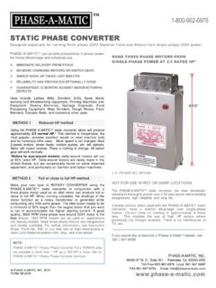
1 STATIC PHASE CONVERTER. INSTRUCTION SHEET . CAUTION: Read the following carefully before NOTE: Mount converter upright with the junction box on the top. The sideways diagram as shown here is to suit the illustration space only. attempting installation. Using the Phase-A-Matic converter as in Method No. 1 METHOD INSTALLATION: will produce approximately 2/3 rated horsepower. Static Phase Converter used to start the load motor Heavily loaded applications, such as compressors, 1. 220V single-phase lines L1 and L2 are connected to the A and blowers, water pumps, hydraulic pumps, etc., the motor C terminals of the converter. pulley diameter must be reduced by 1/3 or a 50% larger motor must be fitted. Otherwise, Method No. 2, shown on 2. Do not connect 220V power, or a ground or neutral wire from reverse side of this page, could be used.
2 Or, use our full the utility, to the B terminal of the converter, as the resulting dead power Phase-A-Matic Rotary Phase Converter. short would damage it instantly. The single-phase neutral wire is not required for operation of the converter. SELECTION: 3. Properly ground all electrical equipment for safety. Use a The horsepower range of the Phase-A-Matic static grounding clip to attach the ground wire to the conduit box. converter is determined by the minimum and maximum 4. Fuses should not be used on the three-phase lines between starting current applied to it at any one time. The largest the Phase-A-Matic static phase converter and the motor. motor on your machine, or the idler motor, if used, must fall A blown fuse still leaves two lines to conduct, which can within the minimum and maximum horsepower range marked damage the converter.
3 Magnetic starters are preferred. Fuses on the Phase-A-Matic static converter. However, after can be used on the single-phase lines L1 and L2 from the the first motor (or idler motor ) has started, motors below utility power to the converter. Single-phase wires and fuses the minimum range may then be started and can usually be should be sized as appropriate for the rated amperage of the left running as the main motor is stopped and started. Do not motor. See chart below. add the horsepower of the power feed, coolant pump, etc. These rely on the generator effect of the main motor. The 5. Size the breaker on the single-phase approximately twice the only time you would add the horsepower of two or more amperage rating of the motor at the 220V configuration. See motors together would be if they always start at exactly the chart below.
4 Same time. Do not install a larger size or Heavy Duty series 6. For machines with magnetic switchgear, resistive or Phase-A-Matic static converter thinking it will give you single-phase load: Resistive or single-phase loads and/or more horsepower. A static converter that is too large will not magnetic switchgear must be connected only to lines A and C. work properly and may cause damage. from the converter. DO NOT connect the Phase-A-Matic . Two-speed motors are dual horsepower. Select the static phase converter until you identify which two wires Phase-A-Matic static phase converter with minimum and operate the magnetics. To easily locate these two wires, maximum horsepower ratings, which fall within or very close connect 220V single-phase power to any 2 of the 3 wires on to the minimum and maximum horsepower of the motor.
5 For the machine and press the start button. When the correct example: A HP 3450 RPM motor is HP at 1725 RPM. combination is found the magnetics will work. Connect these two wires to the outside terminals of the Phase-A-Matic . Some European soft-start motors draw less starting current converter, terminals A and C, and the third wire to the center than normal and therefore require a smaller than normal terminal, B. The magnetics should still work with the center converter. Most Taiwanese and Chinese motors draw greater terminal (line B) disconnected. Your motor's magnetic amperage to start than normal. Therefore, for these motors overload protection remains the same; no changes are we recommend model PAM-600HD for a 3 HP motor; model necessary. PAM-900HD for a 5 HP motor; model PAM-1200HD for a HP motor, etc. 7. For indoor use only.
6 Do not use in wet or damp locations. 8. Do not mount on equipment with excessive vibrations. WHEN TO USE HEAVY DUTY SERIES. 9. Refer to NEC Code #455 for details on field installation issues. Lathes above 3 HP not fitted with a clutch. Air compressors, the motor pulley diameter must be Breaker & Wire Size - Refer to NEC Code #430 C. reduced by 1/3, or a 50% larger motor must be fitted. Long, heavy starting cycles, frequent starting or instant HP 1 2 3 5 10 15 20 25 30 40 50. reversing, unattended motors, if jogging is required, or if Breaker 15 15 20 30 40 60 100 125 160 200 250 300. there is a chance of the motor being stalled during use. Amps Wire Size 300. Gauge 14 14 12 10 8 6 3 1 1/O 3/O 4/O. mcm Phase-A-Matic , INC. Fuses* 10 10 15 30 40 45 60 80 100 125 150 200. 39360 3rd St. E., Suite 301. Conduit Palmdale, Ca.
7 93550-3255 1/2 1/2 1/2 1/2 1/2 1/2 3/4 1 1 1-1/4 1-1/4 1-1/2. Size In. 661-947-8485 FAX 661-947-8764. *Fuses, if used, are time delay, dual element for 1-phase lines E-mail: L-1 and L-2 only; do not use on 3-phase lines to the motor. 2018 Phase-A-Matic , INC. FORM NO. SIS-2018. 1. Phase-A-Matic . STATIC PHASE CONVERTER. OPERATION METHOD NO. 2 INSTALLATION: For multiple motor applications, the largest motor must Static Phase Converter used to start an Idler Motor, Idler Motor always start first, and it must be at least 50% larger than any to power the load motor. other motor starting on the same converter, or if they start simultaneously the combined horsepower of all the motors Full or close to full horsepower (HP) can usually be obtained by must fall within the rating of the converter. powering the load motor through a 3-phase motor that runs on Always start a machine out of gear or in lowest spindle speed single-phase.
8 A Phase-A-Matic static phase converter is used at initial hook-up to reduce load. The Phase-A-Matic static to start the idler motor. The idler motor windings act as a rotary converter has a built-in weak link, which is designed to fail transformer or generator and consume little power when running rapidly if hooked to a higher horsepower motor. On lower unloaded. Used motors are inexpensive and readily available. A. horsepower motors the light could stay on after the motor is single machine or complete shop can be operated with great running, causing rapid failure of the Phase-A-Matic flexibility using this method. The idler motor should be at least 50%. converter, thus providing protection against possible motor larger than the largest motor you want to run to accommodate the damage. higher starting current. A good quality 3450 RPM, Y-wound, 3.
9 Phase, 220 V motor is the best choice. A 1725 RPM motor can be The red indicator light should only come on when the motor used on applications not heavily loaded. is starting and should go out once the motor has reached operating speed. The light should never stay on longer than 3- 1. Wire the Phase-A-Matic static phase converter to the idler 5 seconds since the converter could be damaged if it stays on motor as described in Method No. 1, side 1. longer. When testing the static converter for the first few times 2. Size fuses and wires on the single-phase side as appropriate after installation, keep your hand near the off switch of the for the motor's rated amperage. Once running, the idler motor machine, ready to turn it off to prevent damage to the converter can then power the load motor. Wire the load motor in parallel due to a wrong or loose connection.
10 To the idler motor as per Method No. 2 diagram below. Size Power may be left on the converter without the load applied. fuses and wires on the 3-phase side as appropriate for the Current draw is approximately 8mA (.008 amp). The converter motor's rated amperage. operates best when mounted vertically with the conduit box on 3. Resistive or single-phase loads and/or magnetic switch gear top. Installation should be performed by a qualified electrician. must be energized only by lines A and C from the converter. Refer to local codes for proper wire sizing. Wires and fuses should be sized as appropriate for the motor's rated amperage. See chart on side 1. This unit is not recommended for use with Extra Precautions for Idler Motor System phase-loss monitors. Heavy starting load motor(s) may cause the output voltage of the idler motor on line B to drop sufficiently to cause the static converter ---------------------------------- to return to the start-up mode.