Transcription of Instructions and Advices to use the electronic …
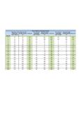
1 Rev. 1 Instructions and Advices to use the electronic controller Logik 25-S ORIGINAL Instructions (I NDUSTRIAL CONTROL EQUIPMENT)39UG FILE: E316817 Rev. 2 INDEX CAUTIONS Page 3 TECHNICAL FEATURES Page 4 MOUNTING Page 5 ELECTRICAL DRAWINGS AND LEGEND OF THE CONNECTION Page5 CONNECTION THROUGH SERIAL PORT RS232 Page 8 CONTROL PANEL Page 9 MENU FLOW Page 10 MAIN MENU Page 11 SETTING C/F , BAR/PSI, LANGUAGE Page 11 VISUALIZATION AND SETTING OF THE PARAMETERS USER LEVEL Page 12 ENTER THE PASSWORD Page 12 VISUALIZATION OF THE MENU Page 12 VISUALIZATION AND SETTING OF THE PARAMETERS Page 12 MENU 0 = WORKING PRESSURES Page 13 MENU 3 = TEMPERATURES Page 13 MENU 5 = WORKING TIMER Page 13 MENU 6 = OIL FILTERS/HOURS Page 13 MENU 7 = WORKING HOURS Page 14 MENU 8 = MAINTENANCE Page 14 MENU 9 = ALARMS Page 15 MENU 10 = RESET Page 15 MENU 11 = COMPRESS.
2 CONFIG. Page 16 MENU 12 = CLOCK TIMER Page 17 MENU 13 = CHANGE PASSWORD Page 18 ALARMS WITH IMMEDIATE COMPRESSOR SHUT OFF Page 18 ALARMS WITH COMPRESSOR SHUT OFF AFTER 30 SECONDS UNLOAD RUN Page 18 WARNINGS (VISUAL ALARMS) Page 19 MESSAGES VISUALIZED IN ALARM LIST ONLY Page 19 MAINTENANCE MESSAGES Page 19 HOW LOGIK 25/S CONTROLS THE COMPRESSOR Page 20 MASTER/SLAVE OPERATION Page 22 WARRANTY TERMS Page 23 Rev. 3 CAUTIONS THE LOGIK 25-S IS AN INDUTRIAL CONTROL EQUIPMENT (NOT A SAFETY INSTRUMENT) FOR THE OPERATION OF A SCREW COMPRESSOR. THE INSTALLATION MUST BE MADE IN ACCORDANCE TO THE LOCAL AND INTERNATIONAL STANDARDS AND REGULATIONS WHERE THE COMPRESSOR IS MANUFACTURED. THE INSTALLATION AND START UP OF THE CONTROLLER MUST BE CARRIED OUT BY TRAINED PERSONNEL WELL KNOW IN THIS MANUAL.
3 THE CONTROLLER HAS TO BE USED IN STANDARD INDUSTRIAL ENVIRONMENT AND IT CAN NOT BE USED IN EXPLOSION RISK ENVIRONMENT, MARITIME AND MILITARY PURPOSE. THIS MANUAL COULD BE SUBJET TO CHANGES; PLEASE CONTACT LOGIKA CONTROL TECHNICAL OFFICE IN CASE OF DOUBT ON THE LAST VERSION. Rev. 4 TECHNICAL FEATURES / Industrial control equipment for the operation and management of screw compressors only; don t mount and use in explosive room. / In accordance to CE regulation: Low tension: 2006/95/CE Safety: EN 60730/1 (General regulations) EMC 2004/108/CE / In accordance to UL 508 (FILE #: E316817). / Inputs and outputs via terminal/block board to wires (300V, 15A, 18/14 AWG). / Black auto/extinguishing box in ABS: a)according CE: IP64 for the front panel and IP20 for the other parts; b)according UL: Type 1 and Type 12 for front panel mounting , installation in pollution degree 2 for the other parts / Tightening torque: 8 Nm / Working temperature: 0 C (32 F) 50 C (122 F) 90% RH (non condensing).
4 / Storage temperature: /20 (/4 F) +70 C (158 F). / Power supply: 12 Vac 10% 50 60 Hz. (power of the transformer s secondary: ~ 9 VA) from safety transformer. / Max. current absorbed = ~ 350 / Visualization through back light alphanumerical LCD 20 digits x 2 rows and nr. 1 led for alarm status. / Messages selectable in 8 languages: Italian English French German Spanish Portuguese Turkish Russian. / nr. 5 key buttons: increase, decrease, enter, start, stop. / nr. 1 input for temperature probe. / nr. 1 input for pressure transducer. / nr. 1 input for PTC or Klicson for motor protection (IN8). / nr. 7 opto isolated digital inputs from 12/24 Vac to detect: IN 1 = emergency stop button IN 2 = thermal motor IN 3 = thermal fan IN 4 = remote start/stop IN 5 = air filter pressure switch IN 6 = separator filter differential pressure switch IN 7 = settable as: door of the electrical cabinet open control phase relay generic alarm / nr.
5 3 digital inputs for connection to Logika Control phases unit. / nr. 7 outputs via relay with contact max. (general use): RL1 = line contactor RL2 = delta contactor RL3 = star contactor RL4 = load solenoid valve RL5 = fan contactor RL6 = settable as: condensate drain solenoid valve or compressor status RL7 = settable as: alarm output or compressor status MAX. RATED CURRENT WITH ALL RELAYS CLOSED: / nr. 1 real time clock with buffer battery, around 10 years electrical life. / nr. 1 serial port RS232 for connection to second compressor (Master/Slave operation), or GSM unit (Super Vision and Tele Assistance). / Check min. and max. power supply to the controller. / Non volatile memory to store setting data, working hours, compressor status, alarm list.
6 / The controller switches OFF due to micro interruption longer than ~ 300 Accessories: / nr. 1 temperature probe KTY for detection of the air end temperature: black cable TPE, length m, working range 10 130 C, resolution 1 C, precision 1 C. / nr. 1 Logika Control phases unit. / nr. 1 pressure transducer 4/20 mA for working pressure control: 2 wires, AISI 316L stainless steel membrane, working range 0 15 bar, resolution 0,1bar, precision 0,1bar. / Windows application for remote control (Super Vision and Tele Assistance). / nr. 1 Logika Control phases unit: a) for power supply 380 400V three phaseb) for power supply 230V three phasec) for power supply 440 460V three Rev. 5 MOUNTING Use the drawing below as overall dimensions to mount the controller.
7 ELECTRICAL DRAWING AND LEGEND OF THE CONNECTIONS OVERALL DIMENSIONS 161 mm 106 mm NOTES ON THE CONNECTIONS Respect the working technical features and Instructions on the electrical wiring; in special way both the cables of the temperatures probes and pressure transducers must be isolated from the power cables and proper RC filters must be placed on the contactors coils. Besides pay attention low voltage and high voltage cables run on separate trunks. - On the back side of the controller there must be enough space for wiring and connectors. - The rear side of the controller must be protected against condensation, oil and dust. - Don t wash the front panel by water injection; clean the front mylar with a soft cloth using soap water. NOTE: the inputs not used have to be connected to 12-24V directly, except IN5 if not used has not to be Rev.
8 6 LEGEND Terminal M1 Pole 1/2 = power supply 12 Vac Terminal M2 RS 232 Pole 1 = GND Pole 2 = RX Pole 3 = TX Pole 4 = +12 Vdc Terminal M3 Pole 1/2 = air end temperature probe Pole 3/4 = pressure transducer (pole 3 = negative pole 4 = positive) Terminal M4 Pole 1 = pole 5 of the control phases (GND) Pole 2 = pole 1 of the control phases (T) Pole 3 = pole 2 of the control phases (S) Pole 4 = pole 3 of the control phases (R) NOTE: THE GND FROM THE CONTROL PHASES UNIT MUST NOT BE CONNECTED TO EARTH. IT S THE GROUND OF THE CONTROLLER AND MUST BE CONNECTED TO IT. Terminal M5 Pole 1 = IN 1 = emergency stop button (L) Pole 2 = IN 2 = thermal motor (L) Pole 3 = IN 3 = thermal fan (L) Pole 4 = IN 4 = remote start/stop (L) Pole 5 = IN 5 = air filter pressure switch (L) Pole 6 = IN 6 = separator filter differential pressure switch (L)
9 Pole 7 = neutral = 0 Vac Terminal M6 Pole 1 = RL7 = alarm or compressor status Pole 2 = RL6 = condensate drain solenoid valve or compressor status Pole 3 = RL5 = fan contactor Pole 4 = RL4 = solenoid valve Pole 5 = RL3 = star contactor Pole 6 = RL2 = delta contactor Pole 7 = RL1 = line contactor Pole 8 = common = 24 230 Vac Terminal M7 Pole 1/2 = IN 8 = PTC or Klicson for motor protection Total resistance of operation = ohm Total resistance of restoration = ohm Pole 3 = IN 7 = settable as door of electrical cabinet open control phase relay generic alarm (L) Rev. 7 EXAMPLE OF CONNECTION TO THE SECURITY PRESSURE SWITCH Contactors 230 Vac If the operation of the contactors and solenoid valves comes through 230 Vac, the digital inputs have to be connected to 12 Vac; next to the contact of the pressure switch, place and energize an auxiliary relay and put the contact in serie to 12 Vac (L) (see drawing on the right).
10 When the pressure switch is closed, the auxiliary relay with contact closed supply power to the digital inputs; the power supply of the controller is connected before the contact of the relay. When the pressure switch opens, the auxiliary relay opens power to the digital inputs; the controller detects all the digital inputs open and signal the alarm SEC. PRESSURE SWITCH . Contactors 24 Vac If the operation of the contactors and soenoid valves come through 24 Vac, the digital inputs have to be connected to 24 Vac (see drawing on the right); on this way when the pressure switch opens due to high pressure, 24 Vac lacks and deenergize all the contactors, solenoid valve and digital: the controller detects all the digital inputs opened and signal the alarm SEC. PRESSURE SWITCH.