Transcription of Instructions and parts List - #79014 V-2 AIR / HYDRAULIC ...
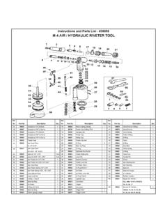
1 ' ' :LR-020V05101 Instructions and parts List - #79014 Repair Kit --6, 7, 8, 9, 10, 11, 18, 21, 37 Service Kit 15, 16(x2), 19, Back Up RingRK95944 Frame Lock NutSetting Screw PinValve Cap O-Ring , 25, 26, 38, 49, 51, 52, 53, 54, 55, 56 Rubber CushionSK95945 Air CylinderO-Ring CapCollar O-Ring P5 Safety Cap Valve Spring Return SpringValve Hanging ClipValve CollarO-Ring PusherBack Up RingValve SpringFrameLever PinOil PistonValve Pusher O-Ring P7 Back Up RingConnectorO-Ring LeverFrame HeadTrigger RodCase Lock NutTriggerJaw Pusher SpringTrigger PinFrame Cap O-Ring 27x2 ConnectorJaw PusherSpanner GagueCase Washer RingSpannerJaw Case RearCylinder O-Ring CapValve CapAir Piston Disc BottomJaw Case Front Air Piston RingNosepiece(1/8") ( )Air Piston Lock NutNosepiece(3/32") ( )Air Piston Disc TopNosepiece(3/16") ( )Air Piston StemNosepiece(5/32") ( )Air Piston Al V-2 AIR / HYDRAULIC RIVETER TOOLPart InformationThe Marson ValueRivet V-2 pneumatic/ HYDRAULIC riveting tool isdesigned to set rivets in all materials in sizes from 3/32 to 3/16 diameter.
2 Model V-2 is supplied with 3/16 NOSEPIECE (1)installed in the operating position. Standard nosepieces for 3/32 (4),1/8 (3) and 5/32 (2) diameter rivets is included among theaccessories supplied with the Maximum Air Pressure is 95 PSI At Setting Capacity 3/16 diameterTraction power 1940 lbsOperating air pressure 85-95 PSIAir consumption 4 CFMAir Inlet 1/4 height Net weight V-2 is packaged in a compartment storage needed to service the tool are included. SpecialSPANNER GAUGE (40) has a cut-out gauge used in adjusting thetool as described included: Safety Cap (25) to catch ejected mandrels whenattached to the back of the order to achieve maximum efficiency and economy, the MarsonV-2 pneumatic/ HYDRAULIC riveting tool should be serviced andmaintained on a regular basis.
3 No special skills or tools other thanthe ones provided are needed to properly service and maintain operative parts of the tools requiring regular inspection andmaintenance are as follows:1. The JAWS (8) should be periodically inspected, cleaned, andwhen necessary, replaced with new jaws (see Cleaning andChanging Jaws under Procedures below).2. The FRAME (17) of the tool should be checked periodically toensure that the oil level is maintained and that there are no leaksor breakdowns in the seals. (See Repair sections underMalfunction for procedures).Maintenance Procedures1. Cleaning and Changing JawsIMPORTANT Disconnect the V-2 from the air pressure linebefore proceeding with inspection or repairs. Use SPANNER (41)to remove FRAME HEAD (13). Use SPANNER GAUGE (40) toremove JAW CASE FRONT (6) while at the same time holding theJAW CASE REAR (7) with the SPANNER (41) open-end jaws with solvent or a steel brush. Replace with new jaws ifexcess wear is apparent.
4 Always coat outer or smooth surface ofjaws with an oil film before by reversing order of above procedure. It is importantthat JAW PUSHER (3) engages the conical parts of the JAWS. DONOT CHANGE THE POSITION OF parts (7) and (14). Ifthese parts are inadvertently changed, see readjustment instructionsunder Malfunction. 2. Changing NosepieceConnect V-2 to air pressure and press TRIGGER (45) until nosepiecehas been removed and new nosepiece fully tightened. WhenTRIGGER (45) has been released and tool is at rest there should be acircular opening visible in the Mandrel gripped by JAWS (6) but rivet does not set andmandrel does not break:CAUSE: Low air pressure or loss of : Increase air pressure but do not exceed 100 PSI at sure all fittings including FRAME CAP (23) and FRAMEHEAD (13) are tight. If malfunction persists, add oil as follows:Disassemble AIR CYLINDER (31), FRAME (17) and FRAMEHEAD (13). Before adding oil, check to be sure OIL PISTON (18) isat the bottom of its stroke, by hand pulling JAW CASE FRONT (6)away from FRAME (17).
5 OIL PISTON (18) should bottom its strokeautomatically when removing FRAME HEAD (13). If JAW CASEFRONT (6) moves downward by hand power, then RETURNSPRING (21) must be replaced. Care must be exercised to avoiddamage to O-RINGS (15, 16). Pour MARSON OIL No. 39105 orequivalent into FRAME (17) while tool is upside down. Beforeassembling also check for oil appearing in AIR CYLINDER (31) orFRAME HEAD (13). If oil is found in any of these areas, replace O-RING (15, 16, 27, 28) as needed. Reassemble Mandrel does not enter nosepiece OR fails to : JAW CASE REAR (7) and NUT (14) have : Adjust so that the distance between the plane underside ofthe FRAME (17) and the front edge of the securely-assembled JAWCASE FRONT (6) is approximately 2 -13/16 . This can be measuredwith the cut-out gauge on SPANNER GAUGE (40) beforeassembling FRAME HEAD (13).3. Tool takes more than one stroke under ideal conditions to setrivet and break : Insufficient : See repair Instructions under Malfunction, : Not enough air : Increase air pressure but do not exceed 95 PSI at : Loose : Tighten nosepiece with SPANNER (41).
6 CAUSE: JAW CASE REAR (7) too far : See procedure under Section 2 above. 44 Campanelli , MA. 02072 Tel. (800) 344-9664 Fax (800) 644-2177 Safety glasses should be worn at all times while operating tool.