Transcription of Instructions – Garage Door Operator Model ML700 …
1 Instructions Garage Door Operator Model ML700 -GB,ML750-GB and ML850-GBGBGB0800 317847i114A2804E-GBWARNING: DAMAGE MAY OCCUR TO DOOR OR Operator IFIR PROTECTOR SYSTEM IS NOT INSTALLED. PROTECTOR SYSTEMMUST BE INSTALLED FOR PROPER FUNCTIONING OF THE PROTECTOR SYSTEM INSTALLATION Protector System must be installed when theforce at the edge of the closing door force exceeds400N (40kg). Excessive force will interfere with theproper operation of the Safety Reverse System ordamage the Garage door. Permanently fasten thecaution label adjacent to the wall-mounted door control control button as a reminderof safe operating all existing Garage door locks to avoiddamage to Garage the lighted door control button (or any additionalpush buttons)in a location where the Garage door isvisible, at a height of at least and out of thereach of children.
2 Do not allow children to operatepush button(s) or remote control(s).Serious personalinjury from a closing Garage door may result frommisuse of the opener only when the door is in full view,free of obstructions and opener is properly one should enter or leave the Garage while thedoor is in motion. Do not allow children to play nearthe manual releaseonly to disengage the trolley and, ifpossible, only when the door is not use thered handle to pull the door open or electric power to the Garage door openerbefore making repairs or removing product is provided with a power supply cord ofspecial design which, if damaged, must be replacedby a power supply cord of the same type; such apower supply cord may be obtained and fitted by to comply with the following Instructions may result in serious personal injury or property damage.
3 Read these Instructions carefully The Garage door opener is designed and tested to offer reasonable safe service provided it is installed and operatedin strict accordance with the Instructions in this safety alert symbols mean WARNING a personal safety or property damage instruction. Read theseinstructions : If your Garage has no service entrance door, Model 1702 EML Outside Quick Release must be installed. This accessoryallows manual operation of the Garage door from outside in case of power Garage door balanced. Do not let the garagedoor opener compensate for a binding or stickinggarage door. Sticking or binding doors must berepaired. Garage doors , door springs, cables, pulleys,brackets and their hardware are under extreme tensionand can cause serious personal injury.
4 Do not attemptto loose, move or adjust for Garage not wear rings, watches or loose clothing whileinstalling or servicing a Garage door avoid serious personal injury from entanglement,remove all ropes connected to the Garage doorbefore installing the door and wiring must be in compliance with yourlocal building and electrical codes. Connect the powersupply cord only to properly earthed doors of fiberglass, aluminum or steelmust be substantially reinforced to avoid doordamage. (See page 3.) The best solution is to checkwith your Garage door manufacturer for an openerinstallation reinforcement safety reverse system test is very Garage door MUST reverse on contact with a40mm obstacle placed on the floor.
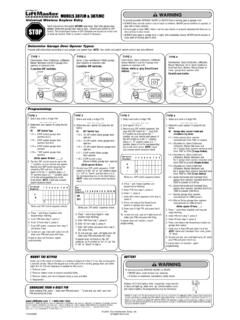
5 Failure to properlyadjust the opener may result in serious personal injuryfrom a closing Garage door. Repeat the test once amonth and make any needed unit should not be installed in a damp or must not extend over public byway by Reading These Important Safety InstructionsBefore You Begin1. Look at the wall or ceiling above the Garage door. The header bracket must be securely fastened to structural Do you have a finished ceiling in your Garage ? If so, a support bracket and additional fastening hardware (not supplied) may be Depending on your door's construction, you might need a special door arm. See your Do you have an access door in addition to the Garage door? If not, Model 1702 EML Outside Quick Release Accessory is Rules.
6 1 Before you Begin .. 1 Door Types .. 1 ..1 Tools Required .. 2 ..2 Hardware Provided .. 2 ..3 Completed Installation .. 2 ..4 Assembly ..2 .. 5-11 Installation .. 2-4 .. 12-21 Install the Protector System .. 4-5 .. 22 Programming your Opener & Remote .. 5 .. 23 Programming your Keyless Entry ..6 ..24 Adjustment .. 6 .. 25-26 Test the Safety Reversal System ..6 ..27 Special Features of theML700-GB, ML750-GB and ML850-GB ..7 .. 28 Quick Release ..7 ..29 Accessories .. 7 .. 30 Replacement Parts .. 7 .. 31-32 Having a Problem? .. 8 Care of your Opener .. 9 Maintenance of your Operator .. 9 Operation of your Opener .. 9 Specifications .. 10 Door Door with Horizontal Track Door with Horizontal and Vertical Track Special door arm (E, The chamberlain Arm )and the Protector System (29 (8)) your Door with Curved Track See 20B connect door arm.
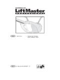
7 The Protector System (29 (8)) is required for doors that are over in door Special door arm (E, The chamberlain Arm )and the Protector System (29 (8)) required. See your chamberlain Arm for use on door types B and SECTIONIMPORTANT: If you have a canopy door, you need to use theinstructions packed with The chamberlain Arm Accessory inconjunction with this owner 's manual when assembling the InstallationAs you proceed with the assembly, installation and adjustmentprocedures in this manual , you may find it helpful to refer back tothis illustration of a completed installation.(1) Header Sleeve(2) Idler Pulley Bracket(3) Trolley(4) Rail(5)Chain/Belt(6) Hanging Bracket(7) Power Cord(8) Opener(9) Light Lens(10) manual Release Rope & Handle(11) Curved Door Arm(12) Straight Door Arm(13) Door Bracket & Plate(14) Header Bracket(15) Trolley Release Arm(1)Hex Bolt (4)(2)Clevis Pin (1)(3)8mm Carriage Bolt (3)(4)Wood Screws (8)(5)Sheet Metal Screws (2)(6)Clevis Pin (2)(7)Rope(8)Handle(9)Insulated Staples (10)(10)Anchor (2)(11)Concrete Anchor (6)(12)Lock Washer (7)(13)Hex Nut (7)(14)Ring Fastener (3)(15)Rail Grease (1)(16) Lock Nut (1)(17)Metric Tapping Screw (4)(18)Hex Screw (3)(19)Spring (1)(20) Flat Washer (2)(21)Stop Bolt (1)(22)Carriage Bolt (2)(23)Wing Nut (2)
8 Hardware Provided34 Assemble the RailGrease inside edges of rail sections using grease (1). Place rail pieces(2) on flat surface for assembly. All four rail sections areinterchangeable. Slide rail brace (3) onto rail section. Connect rail bysliding rail brace onto next rail section. Tap rail assembly (4) on pieceof wood (5) until rail sections are flush. Repeat with remaining the Chain/BeltRemove chain/belt from carton and lay chain out on floor (do not allowchain/belt to twist). A. Chain:Push pins of master link bar (3) through chain link (4) andhole in back end of trolley (5). Push cap (2) over pins and ontonotches. Slide clip-on spring (1) over cap and onto pin notches untilboth pins are securely locked in : If needed, use chain extension link parts to increasechain/cable length (6A).
9 B. Belt: Hook the trolley connector (6) into the slot (7) on the trolley (8).6 Attach Trolley to RailSlide outer trolley (1) into back (opener) end of the rail assembly (2),be sure end with trolley release arm (3) is heading in direction ofopener. Slide outer trolley down rail until it engages with inner Rail to Opener and InstallChain/BeltRemove four washered bolts (1) from top of opener. Place rail (2) onopener, flush with stop (3) on top of opener. Wrap chain/belt (4) oversprocket (5). Push idler pulley bracket assembly toward front of the railto eliminate excess slack in chain/belt. Align bolt holes on brackets (6)with bolt holes on opener. Secure brackets to opener with previouslyremoved bolts. Tighten bolts securely.
10 The opener sprocket teethmust engage the : Use only those bolts mounted in the top of of any other bolts will cause serious damage to Sprocket CoverPlace sprocket cover (1) on top of the opener (2), secure with screws(3). Insert stop bolt (4) into trolley stop hole (5), secure with washer (6)and nut (7).10 Install Header Sleeve and TightenChain/BeltSlide header sleeve (1) onto rail (5). Slide flat washer (3), spring (2)and washer (3) onto carriage bolt (4). Thread nut (6) onto carriage boltuntil finger tight. Use an open end wrench (7) to tighten nut until thechain/belt is not against the inside surface of the rail. See image (8).11 INSTALLATION SECTIONWear protective goggles when working overhead to protect youreyes from all existing Garage door locks to avoid damage to thegarage avoid serious personal injury from entanglement, remove allropes connected to the Garage door before installing the is recommended that the opener be installed 2,1m (7 feet) or moreabove the floor where space the Header BracketThe header bracket must be rigidly fastened to a structuralsupport of the Garage .