Transcription of Instructions - LS-9 Manual - Fuel Injected Wiring …
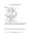
1 installation Instructions . 2009 CORVETTE. LS - 9. 479-243-9115. installation Instructions FOR LS 9. The following Instructions are intended as an aid to assist in harness installation . More in depth information can be obtained by ordering the 2009 GM service Manual (Y-Car Corvette). Troubleshooting techniques and diagnosis are beyond the scope of these Instructions . Diagnostic flow charts and troubleshooting advice are included in the GM service Manual . The general design of the harness allows enough length for computer mounting in the dash & kick panel or under hood area. Special harness lengths can be produced for custom applications on a custom order basis. All harness connections are clearly tagged. If for some reason a tag has been removed, consult the LS 9. Harness layout. Please identify all tags prior to beginning your installation . The following information will briefly discuss the individual harness connections: 1. Blue Computer Plug X1 - 56 pins 2.
2 Black Computer Plug X2 - 73 pins 3. Gray Computer Plug X3 - 73 pins 4. Brake Light Switch Wire (purple) 12V Ignition normally closed switch. This wire must have 12. volts all the time, except when you put the brake on. This will take the torque converter out of lock-up. Use GM switch #255244845. 5. Check Engine Light Wire (brown) For the use of a check engine light. Any 12V automotive light will work. It can be mounted as a permanent fixture in the dash, or used as a diagnostic aid only. The wire is hot when the key in start or run. If light is not used, ensure the brown wire is properly capped. 6. Electric Speedometer Wire (green) 4000 pulse to cruise or electric speedometer. 7. Tach Wire (if desired) (white) Feeds pulse to tachometer. If Tach fails to operate on this pulse, contact Abbott Enterprises, 800-643-5973 for alternate pulse signal simulator. 7. fuel Pump Relay Plug - Starts and stops fuel pump. During key-on runs 2 seconds to load injectors.
3 8. Diagnostic Link Plug (ALDL) Automatic Line Diagnostic Link is used in conjunction with the check engine light and testing or troubleshooting. 9. Fuse Panel - has 9 fuses; (3) 10 amp; (2) 15 amp; (4) 20 amp 10. Ignition Switch Hot Wire (red) The single ignition wire must be connected to provide 12V with the key in START (crank) and RUN position. 12V is then distributed through the fuse block to the computer (ECM), injectors and coil. Each injector bank is fused as is the computer, battery and coil. 11. Battery Wire (orange) Connects to main post on positive side of starter. If you're using a battery disconnect, this lead must go to the hot side of this. 12. Engine Ground Wire (black wire w/soldered aluminum ring terminal) The ground system is critical for proper operation. A good battery to motor and motor to ground is essential. Ground Battery to Motor or Trans (a must)! Ground Motor to Frame and Motor to Body! 13. Hot Feed Electric fuel Pump Wire (brown) Provides 12V to the fuel pump.
4 A fuel pump relay is also provided with the harness and is energized/de-energized by the ECM. 479-243-9115. 14. MAP Sensor Plug (black plug and orange waterproof rubber seal) The Manifold Absolute Pressure (MAP) measures the change in the intake manifold pressure from engine load and speed changes and sends proportional adjustments to the computer. Connect the MAP sensor electronic connecter from the harness to the MAP sensor lead at the rear of the intake manifold. The MAP sensor lead will already be on most new and used engines. 15. Accelerator Pedal Position (9 wire white connector w/grey cap and green waterproof rubber seal). 16. X149 Engine to Ignition Coil - A black plug with a blue face; 14 way conn that plugs into the existing jumper harness that comes with the engine, located on the Pass side at the rear of the fuel rail. This connector feeds into the injectors; coils; and the super charger inlet air pressure sensor. 17. X150 Engine to Ignition Coil - A black plug with a blue face; 12 way conn that plugs into the existing jumper harness that comes with the engine, located on the Driver side at the rear of the fuel rail.
5 This conn feeds into the injectors and coils 18. Knock Sensor (2 wire white connector w/purple and a green waterproof rubber seal). 19. Crank Sensor Plug (3 wire) gray connector w/white cap and purple waterproof rubber seal The crankshaft position sensor (CPS) is located in the lower front of the engine. 20. Passenger Front O2 Plug (4 wire black connector with blue lock on the back) Oxygen Sensor 21. CAM Sensor Plug (3 wire, red, brown, black) black connector w/white cap and purple waterproof rubber seal) The camshaft position sensor (CPS) is located down by the timing cover on the driver side of the engine, and plugs into a jumper harness already on the engine. As the camshaft sprocket turns, a magnet activates the Hall Effect switch in the camshaft position sensor. The CMP Sensor signal is created as piston #1 is approximately 25 degrees after top dead center (TDC) on the power stroke. 22. Vehicle Speed Sensor Plug (VSS) (black connector w/light blue waterproof rubber seal) The vehicle speed sensor is a pulse counter type input that informs the PCM how fast the vehicle is being driven.
6 The VSS system uses an inductive sensor mounted in the tail housing of the transmission and a toothed reluctor wheel on the tail shaft. As the reluctor rotates, the teeth alternately interfere with the magnetic field of the sensor creating an induced voltage pulse. 23. Manual Transmission will have 4 connectors - VSS; Reverse lockout; Skip shift; backup lamp 24. Throttle Position Sensor Plug (6 wire black connector w/gray face) Returns a proportional voltage to the computer that relates to the angular position of the throttle plates. A relaxed throttle-shows low voltage (approx. 8V) and a wide open throttle-shows high voltage (approx ). 25. Alternator (2 wire black connector w/black cap and orange waterproof rubber seal). 26. Mass Air Flow Plug (MAF) (purple connector w/black cap and green waterproof rubber seal) - Located on the air duct, in the front of the intake manifold. Take care when handling the MAF. Do not touch the sensing elements or allow anything to come in contact with them.
7 The PCM converts the mass air flow sensor input signal into grams per second, indicating the amount of air flow entering the engine. 27. Engine Temp Sensor Plug (black connector w/blue waterproof rubber seal) Senses engine coolant temperatures during all operating conditions and signals electric fan operations. Located front head exhaust port. Must use IROC/TA Coolant Sensor #12551708, 3 prong plug on Vette motors. 28. Driver Front O2 Plug (4 wire black connector w/blue lock on back) Oxygen Sensor is located before the Catalytic converter near the exhaust collector pipe. 479-243-9115. 29. Super Charger Coolant Pump - A black 2 wire connector located way out in front of the engine. This pump must be part of the system to supply cooled antifreeze to the super charger. 30. Air Temp Sensor - A Gray 2 wire connector with a light blue seal. This is a separate air temp sensor for the super charger. Located top front pass side of super charger.
8 31. Super Charger By-Pass Valve - A green 2 wire connector with a yellow face. Located up front on the driver side. 32. Barometric Pressure Sensor - A black 3 wire connector with an orange seal, located on the driver side of the super charger. 479-243-9115. COMMON installation QUESTIONS. Q. Is it important to follow any particular order when installing the harness? A. Yes,If mounting the computer inside the car, drill a hole that will accommodate the largest connector on the engine/trans harness into the fire wall behind the valve cover on the pass side head. Feed the harness through a grommet that will fit the hole from the inside of the car through to the engine bay. All the large parts including the computer will remain under the dash. Then, starting at the engine intake manifold, installing the X149 and X150 connectors to help hold the harness in place while completing your installation . The order of installation of the non-engine connectors depends upon your application.
9 Q. What happens if I have a short? A. The quick burn fusible 30 amp link should protect the system in the event of a short. You must find the short before proceeding. Never jumper or bypass around the fusible link. This could damage your harness. Use proper diagnosis and repair techniques. Q. Where can I purchase the Service Manual ? A. Call Helm's at 800-782-4356. Most local auto parts stores have many Helms books. Q. Where can I find professional help with my harness installation ? A. Call Hotwireauto at 479-243-9115. Q. Do you have technical assistance available? A. For technical assistance, call Hotwireauto (479) 243-9115. Q. What should I do if I accidently split or chaff a wire? A. The 2009 Service Manual , Y-Car Corvette, Volume 3 of 4; provides detailed Instructions on repairing damaged wires, etc. Q. If I break a plug or connector, what should I do? A. The 2009 Service Manual , Y-Car Corvette, Volume 3 of 4, provides detailed Instructions on repairing damaged connectors.
10 Q. Can you explain voltage? A. You must use 90 amps or larger alternator with fuel injection. YOU MUST HAVE GOOD. GROUNDS. Battery to motor or trans, engine to frame and engine to body. Q. Do I need to save my old harness? A. No, although it's helpful to save the old harness if you have one for the connectors you can get in case of damage Q. Where can I find the trouble code references? A. Included with you 479-243-9115. WARRANTY DISCLAIMER. No Warranties of any nature (expressed, implied, fitness of usage or merchantability) are given on these products. Seller undertakes no responsibility for any product sold. Additional disclaimers are within and are binding upon this contract. Due to the intended usage of products offered, all products are sold on an as-is basis, and no warranties of any kind, whether written or oral are made by Squier Inc., its agents or employees. All implied warranties, including the implied warranties of merchantability and fitness are expressly excluded, and the buyer bears the entire risk as to quality performance and use of these products.