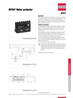
Transcription of INT69 SCY Motor protector - Synchrodan
1 kriwan Industrie-Elektronik GmbH Allmand 11 D-74670 Forchtenberg phone ++49-7947-822-0 fax ++49-7947-1288 e-mail: home: : group AINT69 SCY Motor protectorTechnical dataSupply voltage- dual volageAC 50/60Hz 115/120V +10% 3VA orAC 50/60Hz 230/240V +10% 3VA- AC 24 VAC 50/60Hz 24V +10% 3 VAAmbient temperature +70 CTemperature monitoringPTC, to DIN 44081/082- Number of in Serie- R 25, total< - 20%- 20%- max. lead length<30mAfter thermal trip- Time delay30min 5minPhase monitor3 AC 50/60Hz 10%aktive window t0 + + 6sPhase sequenceLockoutPhase lossTime delay 5min 1min, after10 failures within 24h - AgNi 90/10 (dual voltage)AC 240V, max. , C300min. 24V AC/DC, >20mA- AgNi 90/10 gold-plated (AC 24V)min. >100mV > a single operation at AC/DC>36V or >50mA resistive load, the240V AC relay values applyMechanical service lifeapprox. 1 mio. switching cyclesProtection class acc.
2 To EN 60529IP00 ApprovalUL File Nr. connectors (Faston)Housing MaterialPA66 GF25 MountingScrew mounted or dual voltage22 A 406- dual voltage /gold-plated contacts22 A 406 S22- AC 24V31 A 406 INT69 SCYconnection diagram(suggested)Dimensions in mmApplication:The microprocessor-basedINT69 SCY Motor protectorhas been specially developedto monitor Motor windingtemperature, phase sequenceand phase failure on to technical modification without noticeFuncional description: When supply voltage isapplied, the output relaypulls in after an initialisationperiod of approx. 3seconds, provided allthermistors lie below theirrated response temperature. 1 to 9 PTC thermistors withvaried rated responsetemperatures can beconnected in series to theinput terminals. If any thermistor resistanceincreases above trip level,the output relay drops out. At the same time a 30 minutetime delay is activated,during which the relayremains dropped out.
3 Afterthis period has elapsed andthe thermistor resistance hasdropped below the resetlevel, the relay pulls in again. The phase monitoring functionis active 1 second after motorstart during a 5 secondwindow. Incorrect phasesequence results in lockouttrip. Phase loss results in tripand a subsequent 5 minutereset delay. A maximum of 9 automaticresets following phase loss tripare permitted during a rolling24 hour period. A tenth tripresults in lockout. Lockout and time delay can becancelled by mains reset ofapprox. 5 seconds. To avoid nuisance tripping dueto reverse running aftershutdown (pressureequalisation), the phasemonitoring function is only re-enabled approx. 5 secondsafter Motor stop. The relay is fed out as a N/Odry contact, which is closedunder good unit must be con-nected by trained electricalpersonnel. All valid standardsfor connecting electricalequipment must be ob-served.
4 Limit values for thesupply voltage of the unit maynot be exceeded.