Transcription of INTEGRATED CIRCUITS AND APPLICATIONS
1 INTEGRATED CIRCUITS AND APPLICATIONS Text Books: Design, Morris Mano, 4th Edition INTEGRATED circuit , D. Roy Choudhury 4th edition, New Age International Pvt. Ltd. & Linear ICs, Ramakanth A, Gayakwad , PHI N Nagaraju Asst. Professor Dept. of ECE 1 SYLLABUS 1. Part-1 DIGITAL INTEGRATED CIRCUITS Introduction Various logic families CMOS logic families 2. Part-2 LINEAR INTEGRATED CIRCUITS INTEGRATED CIRCUITS . Op-Amp APPLICATIONS Active Filters & Oscillators Timers & Phase Locked Loop 3. Part-3 DATA CONVERTER INTEGRATED CIRCUITS D-A & A-D Converters 2 PART-1 DIGITAL INTEGRATED CIRCUITS 3 Introduction Introduction to digital INTEGRATED CIRCUITS . CMOS devices and manufacturing technology. CMOS inverters and gates. Propagation delay, noise margins, and power dissipation.
2 Sequential CIRCUITS . Arithmetic, interconnect, and memories. Programmable logic arrays. Design methodologies. What will you learn? Understanding, designing, and optimizing digital CIRCUITS with respect to different quality metrics: cost, speed, power dissipation, and reliability 4 Digital INTEGRATED CIRCUITS Introduction: Issues in digital design The CMOS inverter Combinational logic structures Sequential logic gates Design methodologies Interconnect: R, L and C Timing Arithmetic building blocks Memories and array structures 5 Introduction Why is designing digital ICs different today than it was before? Will it change in future? 6 ENIAC - The first electronic computer (1946) 7 The Transistor Revolution 8 First transistor Bell Labs, 1948 The First INTEGRATED circuit 9 First IC Jack Kilby Texas Instruments 1958 10 Intel 4004 Micro-Processor 1971 1000 transistors 1 MHz operation Intel 8080 Micro-Processor 1974 4500 transistors 12 Intel Pentium (IV) microprocessor 2000 42 million transistors GHz 13 Basic Components In VLSI CIRCUITS Devices Transistors Logic gates and cells Function blocks Interconnects Local interconnects Global interconnects Clock interconnects Power/ground nets 14 Cross-Section of A Chip CMOS transistors 3 terminals in CMOS transistors: G: Gate D: Drain S.
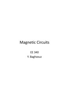
3 Source nMOS transistor/switch X=1 switch closes (ON) X=0 switch opens (OFF) pMOS transistor/switch X=1 switch opens (OFF) X=0 switch closes (ON) An Example: CMOS Inverter X F = X Logic symbol X F = X +Vdd GRD Transistor-level schematic Operation: X=1 nMOS switch conducts (pMOS is open) and draws from GRD F=0 X=0 pMOS switch conducts (nMOST is open) and draws from +Vdd F=1 The CMOS Inverter: A First Glance V in V out C L V DD CMOS Inverter Polysilicon In Out V DD GND PMOS 2l Metal 1 NMOS OutInVDDPMOSNMOSC ontacts N Well Two Inverters Connect in Metal Share power and ground Abut cells VDDCMOS Inverter First-Order DC Analysis VOL = 0 VOH = VDD VM = f(Rn, Rp) V DD V DD V in 5 V DD V in 5 0 V out V out R n R p CMOS Inverter: Transient Response t pHL = f(R on .C L ) = R on C L V out V out R n R p V DD V DD V in 5 V DD V in 5 0 (a) Low-to-high (b) High-to-low C L C L Voltage Transfer Characteristic PMOS Load Lines V DSp I Dp V GSp = V GSp =-1 V DSp I Dn V in =0 V in = V out I Dn V in =0 V in = V in = V DD +V GSp I Dn = - I Dp V out = V DD +V DSp V out I Dn V in = V DD +V GSp I Dn = - I Dp V out = V DD +V DSp CMOS Inverter Load Characteristics IDnVoutVin = = 2 Vin = = 0 Vin = = 1 NMOSVin = 0 Vin = = 1 Vin = = 2 Vin = = 1 Vin = Inverter VTC resPMOS offNMOS satPMOS satNMOS offPMOS resNMOS s atPMOS resNMOS resPMOS satSwitching Threshold as a function of Transistor Ratio 10 0 10 1 1 M V (V)
4 W p /W n Determining VIH and VIL V OH V OL V in V out V M V IL V IH A simplified approach Determining VIH and VIL V OH V OL V in V out V M V IL V IH A simplified approach Determining VIH and VIL V OH V OL V in V out V M V IL V IH A simplified approach Determining VIH and VIL V OH V OL V in V out V M V IL V IH A simplified approach Determining VIH and VIL V OH V OL V in V out V M V IL V IH A simplified approach 32 PART-2 LINEAR INTEGRATED CIRCUITS UNIT-I INTEGRATED CIRCUITS Classification, Chip size & circuit complexity, Ideal & Practical Op-Amp, Op-Amp Characteristics - DC & AC Characteristics, 741 Op-Amp & its features, Modes of operation Inverting and Non-Inverting, differential. 33 34 An INTEGRATED circuit (IC) is a miniature ,low cost electronic circuit consisting of active and passive components fabricated together on a single crystal of silicon.
5 The active components are transistors and diodes and passive components are resistors and capacitors. INTEGRATED CIRCUITS 35 Advantages of INTEGRATED CIRCUITS and hence increased equipment density. reduction due to batch processing. system reliability due to the elimination of soldered joints. functional performance. devices. operating speeds. in power consumption CLASSIFICATION OF ICs INTEGRATED CIRCUITS offer a wide range of APPLICATIONS and could be broadly classified as: Ics 2. Linear Ics Based on these two requirements. Two distinctly different IC Technology namely Technology and 2. Hybrid Technology 36 CLASSIFICATION OF ICs 37 circuit COMPLEXITY &CHIP SIZES In the early days ( up until the 1950s) the electronics device Technology was dominated by the vacuum tube Now days electronic is the result of the invention of the transistor in 1947 The invention of the transistor by William B, Shockley , Walter H,brattain and john Barden of bell telephone laboratories was followed by the development of the INTEGRATED circuit The size and complexity of Ics have increased rapidly A) Invention of Transistor (Ge) 1947 B) Development of silicon transistor 1955-1959 C) Silicon planar technology 1959 D) First Ics , Small Scale Integration (SSI) 1960-1965 E) Medium scale Integration (MSI) 1965-1970 F) Large scale integration (LSI) 1970- 1980 G)Very Large scale integration (VLSI) 1980- 1990 H)
6 Ultra Large scale integration (ULSI) 1990-2000 I) Giant - scale integration (GSI) 38 39 OPERATIONAL AMPLIFIER An operational amplifier is a direct coupled high gain amplifier consisting of one or more differential amplifiers, followed by a level translator and an output stage. It is a versatile device that can be used to amplify ac as well as dc input signals & designed for computing mathematical functions such as addition, subtraction ,multiplication, integration & differentiation 40 Op-amp symbol Non-inverting input inverting input 0utput +5v -5v 2 3 6 7 4 41 IC packages available can package. package. flat package. Ideal characteristics of OPAMP Infinite voltage gain Ad Infinite input resistance Ri, so that almost any signal source can drive it and there is no loading of the input source. Zero output resistance RO, so that output can drive an infinite number of other devices.
7 Zero output voltage when input voltage is zero. Infinite bandwidth so that any frequency signal from 0 to infinite Hz can be amplified without attenuation. Infinite common mode rejection ratio so that the output common mode noise voltage is zero. Infinite slew rate, so that output voltage changes occur simultaneously with input voltage changes. 42 INTERNAL circuit OF IC 741 43 DIFFERENTIAL AMPLIFIER 44 MODES OF DIFFERENTIAL AMPLIFIER The four differential amplifier configurations are following: Dual input, balanced output differential amplifier. Dual input, unbalanced output differential amplifier. Single input balanced output differential amplifier. Single input unbalanced output differential amplifier. 45 Different configurations of DA 46 LEVEL TRANSLATOR & BUFFER 47 IC 741 COMPLETE circuit 48 49 Inverting Op-Amp VVRROUTINf 150 Non-Inverting Amplifier VVRROUTIN 11251 Voltage follower 52 DC characteristics Input offset current The difference between the bias currents at the input terminals of the op- amp is called as input offset current.
8 The input terminals conduct a small value of dc current to bias the input transistors. Since the input transistors cannot be made identical, there exists a difference in bias currents 53 DC characteristics Input offset voltage A small voltage applied to the input terminals to make the output voltage as zero when the two input terminals are grounded is called input offset voltage 54 DC characteristics Input offset voltage A small voltage applied to the input terminals to make the output voltage as zero when the two input terminals are grounded is called input offset voltage 55 DC characteristics Input bias current Input bias current IB as the average value of the base currents entering into terminal of an op-amp IB=IB+ + IB- 2 56 DC characteristics THERMAL DRIFT Bias current.
9 Offset current and offset voltage change with temperature. A circuit carefully nulled at 25oc may not remain so when the temperature rises to 35oc. This is called drift. 57 AC characteristics Frequency Response HIGH FREQUENCY MODEL OF OPAMP 58 AC characteristics Frequency Response OPEN LOOP GAIN VS FREQUENCY 59 Frequency compensation methods Dominant- pole compensation Pole- zero compensation 60 Slew Rate The slew rate is defined as the maximum rate of change of output voltage caused by a step input voltage. An ideal slew rate is infinite which means that op-amp s output voltage should change instantaneously in response to input step voltage 61 Need for frequency compensation in practical op-amps Frequency compensation is needed when large bandwidth and lower closed loop gain is desired. Compensating networks are used to control the phase shift and hence to improve the stability 62 APPLICATIONS of Op Amp BASIC APPLICATIONS OF OP-AMP Scale changer/Inverter.
10 Summing Amplifier. Inverting summing amplifier Non-Inverting summing amplifier. Subtractor Adder - Subtractor 63 64 65 66 67 68 Instrumentation Amplifier In a number of industrial and consumer APPLICATIONS , the measurement of physical quantities is usually done with the help of transducers. The output of transducer has to be amplified So that it can drive the indicator or display system. This function is performed by an instrumentation amplifier 69 Instrumentation Amplifier 70 Features of instrumentation amplifier gain accuracy CMRR gain stability with low temperature co- efficient dc offset output impedance AC AMPLIFIER 71 V to I Converter 72 I to V Converter 73 74 Sample and hold circuit A sample and hold circuit is one which samples an input signal and holds on to its last sampled value until the input is sampled again.