Transcription of Integrated Dual RF Receivers Data Sheet ADRV9008-1
1 Integrated Dual RF Receivers Data Sheet ADRV9008-1 Rev. 0 Document Feedback Information furnished by analog Devices is believed to be accurate and reliable. However, no responsibility is assumed by analog Devices for its use, nor for any infringements of patents or other rights of third parties that may result from its use. Specifications subject to change without notice. No license is granted by implication or otherwise under any patent or patent rights of analog Devices. Trademarks and registered trademarks are the property of their respective owners. One Technology Way, Box 9106, Norwood, MA 02062-9106, Tel: 2018 analog Devices, Inc. All rights reserved. Technical Support FEATURES Dual Receivers Maximum receiver bandwidth: 200 MHz Fully Integrated , fractional-N, RF synthesizers Fully Integrated clock synthesizer Multichip phase synchronization for RF LO and baseband clocks JESD204B datapath interface Tuning range (center frequency): 75 MHz to 6000 MHz APPLICATIONS 3G/4G/5G FDD, macrocell base stations Wideband active antenna systems Massive multiple input, multiple output (MIMO) Phased array radar Electronic warfare Military communications Portable test equipment GENERAL DESCRIPTION The ADRV9008-1 is a highly Integrated , dual radio frequency (RF), agile receiver offering Integrated synthesizers and digital signal processing functions.
2 The IC delivers a versatile combination of high performance and low power consumption required by 3G/4G/5G macrocell, frequency division duplex (FDD), base station applications. The receive path consists of two independent, wide bandwidth, direct conversion Receivers with state-of-the-art dynamic range. The complete receive subsystem includes automatic and manual attenuation control, dc offset correction, quadrature error correction (QEC), and digital filtering, eliminating the need for these functions in the digital baseband. RF front-end control and several auxiliary functions, such as analog -to-digital converters (ADCs), digital-to- analog converters (DACs), and general-purpose input/outputs (GPIOs) for the power amplifier (PA), are also Integrated . In addition to automatic gain control (AGC), the ADRV9008-1 also features flexible external gain control modes, allowing dynamic gain control. The received signals are digitized with a set of four, high dynamic range, continuous time, sigma-delta ( - ) ADCs that provide inherent antialiasing.
3 The combination of the direct conversion architecture (which does not suffer from out of band image mixing) and the lack of aliasing reduces the requirements of the RF filters compared to the requirements of traditional intermediate frequency (IF) Receivers . The fully Integrated phase-locked loop (PLL) provides high performance, low power, fractional-N, RF synthesis for the receiver signal paths. An additional synthesizer generates the clocks needed for the converters, digital circuits, and serial interface. A multichip synchronization mechanism synchronizes the phase of the RF local oscillator (LO) and baseband clocks between multiple ADRV9008-1 chips. The ADRV9008-1 features the isolation that high performance base station applications require. All voltage controlled oscillators (VCOs) and loop filter components are Integrated . The high speed JESD204B interface supports up to Gbps lane rates, resulting in a single lane per receiver in the widest bandwidth mode.
4 The interface also supports interleaved mode for lower bandwidths, reducing the total number of high speed data interface lanes to one. Both fixed and floating point data formats are supported. The floating point format allows internal AGC to be invisible to the demodulator device. The core of the ADRV9008-1 can be powered directly from V and V regulators and is controlled via a standard 4-wire serial port. Comprehensive power-down modes are included to minimize power consumption during normal use. The ADRV9008-1 is packaged in a 12 mm 12 mm, 196-ball chip scale ball grid array (CSP_BGA). ADRV9008-1 Data Sheet Rev. 0 | Page 2 of 68 TABLE OF CONTENTS Features .. 1 Applications .. 1 General Description .. 1 Revision History .. 2 Functional Block Diagram .. 3 Specifications .. 4 Current and Power Consumption Specifications .. 8 Timing Diagrams .. 9 Absolute Maximum Ratings .. 10 Reflow Profile .. 10 Thermal Management .. 10 Thermal Resistance.
5 10 ESD Caution .. 10 Pin Configuration and Function Descriptions .. 11 Typical Performance Characteristics .. 17 75 MHz to 525 MHz Band .. 17 650 MHz to 3000 MHz Band .. 25 3400 MHz to 4800 MHz Band .. 33 5100 MHz to 5900 MHz Band .. 40 Receiver Input 45 Terminology .. 46 Theory of Operation .. 47 Receivers .. 47 Clock Input .. 47 Synthesizers .. 47 SPI .. 47 JTAG Boundary Scan .. 47 Power Supply Sequence .. 47 GPIO_x Pins .. 48 Auxiliary Converters .. 48 JESD204B Data Interface .. 48 Applications Information .. 49 PCB Layout and Power Supply Recommendations .. 49 PCB Material and Stackup Selection .. 49 Fanout and Trace Space Guidelines .. 51 Component Placement and Routing Guidelines .. 52 RF and JESD204B Transmission Line Layout .. 58 Isolation Techniques Used on the ADRV9008-1W/PCBZ .. 60 RF Port Interface Information .. 61 Outline Dimensions .. 68 Ordering Guide .. 68 REVISION HISTORY 9/2018 Revision 0: Initial Version Data Sheet ADRV9008-1 Rev.
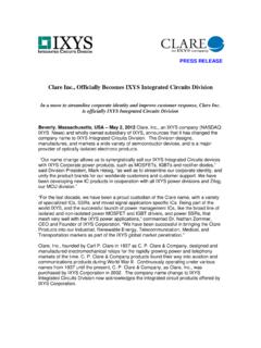
6 0 | Page 3 of 68 FUNCTIONAL BLOCK DIAGRAM RF_EXT_LO_I/O+RX2_IN+RX2_IN RX1_IN+RX1_IN Rx1Rx2 LPFLPFCLOCKGENERATIONSERDOUT0 SERDOUT1 SERDOUT2 SERDOUT3 SYSREF_IN GP_INTERRUPTRX1_ENABLERX2_ENABLETESTSCLK SDOSDIOREF_CLK_IN +REF_CLK_IN DIGITALPROCESSINGDECIMATIONpFIRAGCDC OFFSETQECJESD204 BCIF/RIFRF_EXT_LO_I/O GPIOs, AUXILIARY ADCs,AND AUXILIARY DACsGPIO_3p3_xGPIO_xAUXADC_xADRV9008-1 CSRESETSYNCIN0 SYNCIN1 ADCADC16830-001 ArmCortex-M3RF LOSYNTHESIZER Figure 1. ADRV9008-1 Data Sheet Rev. 0 | Page 4 of 68 SPECIFICATIONS Electrical characteristics at VDDA1P31 = V, VDDD1P3_DIG = V, TJ = full operating temperature range, and LO frequency (fLO) = 1800 MHz, unless otherwise noted. The specifications in Ta b l e 1 are not de-embedded. Refer to the Typical Performance Characteristics section for input/output circuit path loss. The device configuration profile for the 75 MHz to 525 MHz frequency range is as follows: receiver = 50 MHz bandwidth (inphase quadrature (I/Q) rate = MHz), JESD204B rate = GSPS, and device clock = MHz.
7 Unless otherwise specified, the device configuration for all other frequency ranges is as follows: receiver = 200 MHz bandwidth (I/Q rate = MHz), JESD204B rate = GSPS, and device clock = MHz. Table 1. Parameter Symbol Min Typ Max Unit Test Conditions/Comments Receivers Center Frequency 75 6000 MHz Gain Range 30 dB analog Gain Step dB Attenuator steps from 0 dB to 6 dB 1 dB Attenuator steps from 6 dB to 30 dB Bandwidth Ripple dB 200 MHz bandwidth, compensated by programmable finite impulse response (FIR) filter dB Any 20 MHz bandwidth span, compensated by programmable FIR filter Receiver (Rx) Bandwidth 200 MHz Receiver Alias Band Rejection 80 dB Due to digital filters Maximum Useable Input Level PHIGH 0 dB attenuation, increases decibel for decibel with attenuation, continuous wave (CW) = 1800 MHz, corresponds to 1 dBFS at ADC 11 dBm 75 MHz < f 3000 MHz dBm 3000 MHz < f 4800 MHz dBm 4800 MHz < f 6000 MHz Noise Figure NF 0 dB attenuation, at receiver port dB 75 MHz < f 600 MHz 12 dB 600 MHz < f 3000 MHz 13 dB 3000 MHz < f 4800 MHz dB 4800 MHz < f 6000 MHz Ripple dB At band edge maximum bandwidth mode Input Third-Order Intercept Point IIP3 Difference Product 12 dBm 75 MHz < f 600 MHz, (PHIGH 12) dB per tone; 600 MHz < f 6000 MHz, (PHIGH 10) dB per tone; two tones near band edge Sum Product 12 dBm 75 MHz < f 600 MHz, (PHIGH 12) dB per tone; 600 MHz < f 6000 MHz, (PHIGH 10) dB per tone; two tones at bandwidth/6 offset from the LO Third-Order Harmonic Distortion HD3 75 MHz < f 600 MHz, (PHIGH 6) dB; 600 MHz < f 6000 MHz, (PHIGH 4) dB.
8 CW tone at bandwidth/6 offset from the LO 65 dBc 75 MHz < f 600 MHz 66 dBc 600 MHz < f 4800 MHz 62 dBc 4800 MHz < f 6000 MHz Data Sheet ADRV9008-1 Rev. 0 | Page 5 of 68 Parameter Symbol Min Typ Max Unit Test Conditions/Comments Second-Order Input Intermodulation Intercept Point IIP2 62 dBm 75 MHz < f 600 MHz, (PHIGH 12) dB per tone; 600 MHz < f 6000 MHz, (PHIGH 10) dB per tone; 0 dB attenuation, complex Image Rejection 75 dB QEC active, within 200 MHz receiver bandwidth Input Impedance 100 Differential (see Figure 168) Receiver to Receiver Isolation 77 dB 75 MHz < f 600 MHz 65 dB 600 MHz < f 4800 MHz 61 dB 4800 MHz < f 6000 MHz Receiver Band Spurs Referenced to RF Input at Maximum Gain 95 dBm No more than one spur at this level per 10 MHz of receiver bandwidth Receiver LO Leakage at Receiver Input at Maximum Gain Leakage decreases decibel for decibel with attenuation for first 12 dB 70 dBm 75 MHz < f 600 MHz 70 dBm 600 MHz < f 3000 MHz 65 dBm 3000 MHz < f 6000 MHz LO SYNTHESIZER LO Frequency Step Hz GHz to GHz, MHz phase frequency detector (PFD) frequency LO Spur 85 dBc Excludes integer boundary spurs Integrated Phase Noise 2 kHz to 18 MHz 75 MHz LO rms Narrow PLL loop bandwidth (50 kHz)
9 1900 MHz LO rms Narrow PLL loop bandwidth (50 kHz) 3800 MHz LO rms Wide PLL loop bandwidth (300 kHz) 5900 MHz LO rms Wide PLL loop bandwidth (300 kHz) Spot Phase Noise 75 MHz LO Narrow PLL loop bandwidth 10 kHz Offset dBc/Hz 100 kHz Offset dBc/Hz 1 MHz Offset dBc/Hz 10 MHz Offset dBc/Hz 1900 MHz LO Narrow PLL loop bandwidth 100 kHz Offset 100 dBc/Hz 200 kHz Offset 115 dBc/Hz 400 kHz Offset 120 dBc/Hz 600 kHz Offset 129 dBc/Hz 800 kHz Offset 132 dBc/Hz MHz Offset 135 dBc/Hz MHz Offset 140 dBc/Hz 6 MHz Offset 150 dBc/Hz 10 MHz Offset 153 dBc/Hz 3800 MHz LO Wide PLL loop bandwidth 100 kHz Offset 104 dBc/Hz MHz Offset 125 dBc/Hz 10 MHz Offset 145 dBc/Hz 5900 MHz LO Wide PLL loop bandwidth 100 kHz Offset 99 dBc/Hz MHz Offset dBc/Hz 10 MHz Offset dBc/Hz LO PHASE SYNCHRONIZATION Change in LO delay per temperature change Phase Deviation ps/ C ADRV9008-1 Data Sheet Rev.
10 0 | Page 6 of 68 Parameter Symbol Min Typ Max Unit Test Conditions/Comments EXTERNAL LO INPUT Input Frequency fEXTLO 300 8000 MHz Input frequency must be 2 the desired LO frequency Input Signal Power 0 12 dBm 50 matching at the source 3 dBm fEXTLO 2 GHz, add dBm/GHz above 2 GHz 6 dBm fEXTLO = 8 GHz External LO Input Signal Differential To ensure adequate QEC Phase Error ps Amplitude Error 1 dB Duty Cycle Error 2 % Even Order Harmonics 50 dBc CLOCK SYNTHESIZER Integrated Phase Noise 1 kHz to 100 MHz MHz LO rms PLL optimized for close in phase noise Spot Phase Noise MHz 100 kHz Offset 109 dBc/Hz 1 MHz Offset 129 dBc/Hz 10 MHz Offset 149 dBc/Hz REFERENCE CLOCK (REF_CLK_IN ) Frequency Range 10 1000 MHz Signal Level V p-p AC-coupled, common-mode voltage (VCM) = 618 mV, use <1 V p-p input clock for best spurious performance AUXILIARY CONVERTERS ADC Resolution 12 Bits Input Voltage Minimum V Maximum VDDA_ 3P3 V DAC Resolution 10 Bits Includes four offset levels Output Voltage Minimum V 1 V VREF Maximum VDDA_ 3P3 V V VREF Output Drive Capability 10 mA DIGITAL SPECIFICATIONS (CMOS): SERIAL PERIPHERAL INTERFACE (SPI), GPIO_x Logic Inputs Input Voltage High Level VDD_ INTERFAC E VDD_ INTERFACE V Low Level 0 VDD_ INTERFAC E V Input Current High Level 10 +10 A Data Sheet ADRV9008-1 Rev.