Transcription of Interactive Parts Catalog - Winnebago
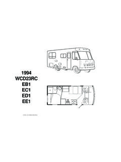
1 Winnebago Industries, Inc. InteractiveParts Catalog Introduction ..2 Parts Graphics 3D 3D Model 2D 2D Image Colored Parts Frequently Asked Welcome to theWinnebago Industries Interactive Parts Catalog a user friendly 3 dimensional (3D) Interactive service Parts Catalog . When you open acatalog page, you will see a split screen (seeFigure1). On the left side of the screen is the Graphics Windowand on the right side of the screen is the Parts List. The Colored Parts Lookup is noted with the color wheelicon . Figure1 On the initialcatalogpage for a model, the Graphics Window containsa view ofthe floorplan, the model name, the series name, and the model year alpha characteras well as the available color codes. The service Parts Catalog has been separated into sections.
2 The Parts List contains links to the available sections. Click on the appropriate link to bring up the initialcatalogpage for that section. Note that some sections are sub divided into additional items included ineach sectionare as follows. Depending upon your unit, you may not have all items listed. Section Contents Chassis Air Spring;Chassis Frame;Exhaust & Fuel Systems;Hitch;Leveling; Mud Flap;Rear Bumper; Step Well;Wheel Door & Compartments Compartments Door Sections;Driver Door;Entry Door;Entry Step Refrigerator Door Vent Drivers Area Beverage Tray; Bucket Seats; Center Console;Curtains;Cushions; Dash; Entertainment Center;FrontInterior; Motor Cover;Seat Belts & Pedestals Electric Antenna;Battery;Body/Chassis/DashWiring; Boxes;Cords;DVD; Exterior Entertainment; Fans;Inverter;Lights;Load Center;Monitor Panel;Radio; Receptacles;Rear Monitor;Switches TV Exterior Air Horn;Awning;Backwall;Body Sections;Decals;Exterior Mirror;Floor; Front Body Panel Front Cap;Graphics Ladder;Mud Flaps; Rear Cap;Running Boards;Sidewalls;Slideout Rooms.
3 Slideout Seatbelts Generator Generator Heating &A/C Auto A/C Central A/C;Furnace;Rear Heater;Roof A/C Interior Appliances;Bed;Cabinet;Chairs;Curtains;C ushions;Decorations Detectors;Doors;Drawers;Grilles;Hardware ;Registers;Seat Belts;Sofa; Shower Door;Tables Labels Labels LP LP System Plumbing Dump Valves;Faucets;Exterior Shower Center;Faucets;Plumbing Fixtures; Pump;Sinks;Shower;Water Heater Windows & Vents Roof Vents;Skylight;Windows;Windshield;Wipers The Unit Toolbar (seeFigure2) is displayed in the upper right corner of the Catalog Window. Note that the values of the MODEL, YEAR, COLOR, SERIAL NUMBER, and DATE fields are carried from Catalog page to Catalog page. Figure2 Parts List The PartsList is located on the right side of the screen. It contains many valuable pieces of information and is arrangedin a multi column format.
4 Thecolumns are as follows: Column Description or or Denotes if the part Number is linked to any geometry part number is linked to geometry and displayed partnumber is linked to geometry and not displayed part number is not linked to any geometry ITEM Item CalloutNumber part NUMBER WinnebagoPart Number UOM Unit of Measure DESCRIPTION Description of the part along withadditionalinformationas applicable Vendor part Number Feature Code used to distinguish between options;see the Service Parts List for your unit to determine which optional features are installed on your unit FromandThru Dates used to note if a part was used in production for aspecificperiod of time Link some Parts may contain a link to anothercatalogpage; simply click on the underlined link to display the subsequent catalogpage NOTE: The Parts List uses anabbreviated description to allow room for the illustration.
5 Be sure to check the service descriptions of the part for important information before ordering. Colored Parts Lookup Converts a colorless part number to a colored part number. See the Colored Parts Lookup section for more information. If you select an item in the Parts List, the item information in the Parts Lists highlights. In addition,any linked3 Dgeometryhighlights in the Graphics Window. If a 2D image is used, there is nolinked geometry, therefore nothing highlights in the Graphics Window. If you double click on an item in the Parts List that is linked to geometry, the 3D view is zoomed in to fitall thelinkedgeometry in the Graphics Windowand the rotation center is setto the center of the selected geometry. If you toggle the check box located at the beginning of the Parts List row, the geometry will toggle between shown (checked) and hidden (un checked).
6 If you right click on an item in the Parts List, a menu will pop up. The first menu lists the ItemCalloutnumber of the part . Clicking onFITwill zoom the 3D view to fitall linkedgeometry in the Graphics Window. You may need to rotate the geometry to see the highlighted part if it is currently hidden. This is the same as double clicking on the item in the Parts List. Clicking onFIT TO SINGLE INSTANCE will zoom the 3D view to fit one instance (not all) of the linked geometry in the Graphics Window. You may need to rotate the geometry to see the highlighted part if it is currently hidden. Clicking onHIDE will toggle the display of the partselectedfrom shown to hidden the menu will then display SHOW. Clicking onSHOW will toggle the display of the partselectedfrom hidden to shown the menu will then display HIDE.
7 UNSELECT willunselect andun highlight the part number and geometry. GO TO SHEET additional Sheets that also contain this part numberwill be listed. Click on a Sheet nameto activate it. SHOW ALL changesall hidden geometry back to shown. ABOUT informational message about the document. There can be morethanone entry for an item number. Multiple part numbers will be defined with Feature Numbers, From/Thru dates, or additional information to distinguish usage. There can be morethanone piece of geometry linked to an item in the Parts List. When a part number is used in multiple locations, it is usually only defined once in the Parts List. The Parts List will utilize an indent feature. The indent feature uses dots ( ) to distinguish between the levels.
8 Sub components of a part will be indented below the preceding main component part number. SeeFigure3. Figure3 part numbers may be repeated in the Parts List to show a relationship to the preceding item. SeeFigure4. Figure4 In certain catalogs, somecomponentsthat are used in many places or may not be available in the 3D modelare grouped together at the end of the Parts List. Headings will group the components together. SeeFigure5. Figure5 You have the ability to filter the Parts List by the manufactured date of the unit. Simply enter the manufactured date of the unit in the DATE fieldlocated in the Unit Toolbar(seeFigure6) and thecatalog will use the FROM and THRU dates to display only those part numbers that were used in production on the date of manufacture.
9 If you enter the eightcharacter abbreviated serial number in the SERIALNUMBER fieldin the Unit Toolbar, the Catalog will automatically get the Manufactured Date of the unit and insert it into the DATE field(see Figure6). The catalogwill use the FROM and THRU dates to display only those part numbers that were used in production on the date of manufacture. Figure6 Graphics Window The left side of the screen is the GraphicsWindow. This iswhere the geometry is displayed either a3 dimensional (3D)model or a2 dimensional (2D)image. Multiple sheets (or scenes)may bedefined on the Catalog page. Use the drop down menuin Graphics Windowtoolbar to select adifferent sheet. See Figure 7. Theseadditional sheets willbe noted in the title of the Catalog page(Figure8).
10 NOTE: The Interior Curtain & Cushions group will almost always have multiple sheets defined by the interior color code of the unit. Please make sure that you are on the correct sheet. Figure7 Figure8 Use the RESET icon on the top toolbar to reset the Graphics Window back to the default orientation. Optional geometry will be placed outsidethe standard 3 Dmodel. SeeFigure9. Figure9 You can print either the Graphics Window (as currently displayed) or the Parts List by using the PRINT GRAPHICS icon or the PRINT TABLE icon on the top toolbar. You can toggle the screen to show Graphics Window and the Parts List or show only the Graphics Window by clicking on the SHOW GRAPHICS ONLY icon on the top Model The 3D model can be rotated, zoomed in or out, and moved around to aid in easily identifying Parts .