Transcription of Interfacing FT2232H Hi-Speed Devices to I2C Bus
1 Use of FTDI Devices in life support and/or safety applications is entirely at the user s risk, and the user agrees to defend, indemnify and hold harmless FTDI from any and all damages, claims, suits or expense resulting from such use. Future Technology Devices International Limited (FTDI) Unit 1,2 Seaward Place, Glasgow G41 1HH, United Kingdom Tel.: +44 (0) 141 429 2777 Fax: + 44 (0) 141 429 2758 E-Mail (Support): Web: Copyright Future Technology Devices International Limited Application Note AN_113 Interfacing FT2232H Hi-Speed Devices to I2C Bus Version Issue Date: 2020-05-26 . 1 Product Page Document Feedback Copyright Future Technology Devices International Limited Application Note AN_113 Interfacing FT2232H Hi-Speed Devices to I2C Bus Version Document Reference No.
2 : FT_000137 Clearance No.: FTDI# 90 Table of Contents 1 Introduction .. 2 I2C Bus Introduction .. 2 2 Sample Project with FT2232H .. 4 Overview .. 4 Sample Circuit .. 4 Sample Code .. 5 Definitions and Functions .. 5 Initialise EEPROM Device .. 7 Program EEPROM Random Byte Address .. 9 Read EEPROM Random Byte address .. 10 Using Channel B Requirements .. 12 3 Contact Information .. 13 Appendix A - References .. 14 Document References .. 14 Acronyms and Abbreviations .. 14 Appendix B - List of Figures and Tables .. 15 List of Figures .. 15 List of Tables .. 15 Appendix C - Revision History .. 16 2 Product Page Document Feedback Copyright Future Technology Devices International Limited Application Note AN_113 Interfacing FT2232H Hi-Speed Devices to I2C Bus Version Document Reference No.
3 : FT_000137 Clearance No.: FTDI# 90 1 Introduction The FT2232H and FT4232H are the FTDI s first USB Hi-Speed (480 Mbits/s) USB to UART/FIFO ICs. They also have the capability of being configured in a variety of serial interfaces using the internal MPSSE (Multi-Protocol Synchronous Serial Engine). The FT2232H device has two independent ports, both of which can be configured using MPSSE while only Channel A and B of FT4232H can be configured using MPSSE. Using MPSSE can simplify the synchronous serial protocol (USB to SPI, I2C, JTAG, etc.) design. This application note illustrates how to use the MPSSE of the FT2232H to interface with the I2C bus.
4 Users can use the example schematic and functional software code to begin their design. Note that software code is provided as an illustration only and not supported by FTDI. I2C Bus Introduction I2C is a low- to medium-data-rate master/slave communication bus. Two wires, serial data (SDA) and serial clock (SCL), carry information between the Devices connected to the bus. Each device is recognized by a unique address and can operate as either a transmitter or receiver, depending on the function of the device. In addition to transmitters and receivers, Devices can also be considered as masters or slaves when performing data transfers.
5 A master is the device which initiates a data transfer on the bus. At that time, any device addressed is considered a slave. The physical layer of I2C bus is a simple handshaking protocol that relies upon open collector outputs on the bus Devices and the device driving or releasing the bus lines, so a pull-up resistor is needed on each wire of the bus. I2C bus is a true multi-master bus including collision detection and arbitration to prevent data corruption if two or more masters simultaneously initiate data transfer Serial, 8-bit oriented, bi-directional data transfers can be made at up to 100 Kbit/s in the Standard-mode of I2C bus, up to 400 Kbit/s in the Fast-mode or up to Mbit/s in the High- speed mode.
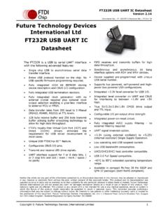
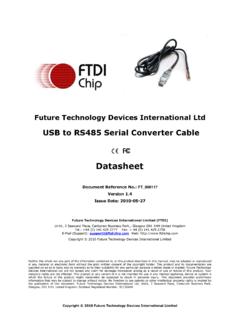
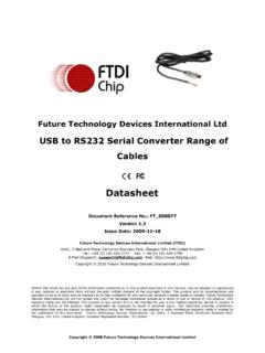
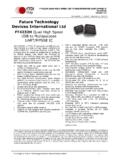
6 Figure 1 shows typical data transfers on the I2C bus. The master supplies the clock; it initiates and terminates transactions and the intended slave (based upon the address provided by the master) acknowledges the master by driving or releasing the bus. The slave cannot terminate the transaction but can indicate a desire to by a NAK or not-acknowledge. Figure 1 Data transfer on I2C bus I2C specification defines unique situations as START (S) and STOP (P) conditions (see Figure 2). A HIGH to LOW transition on the SDA line while SCL is HIGH indicates a START condition. A LOW to HIGH transition on the SDA line while SCL is HIGH defines a STOP condition.
7 START and STOP conditions are always generated by the master. 3 Product Page Document Feedback Copyright Future Technology Devices International Limited Application Note AN_113 Interfacing FT2232H Hi-Speed Devices to I2C Bus Version Document Reference No.: FT_000137 Clearance No.: FTDI# 90 Figure 2 START and STOP conditions Every byte put on the SDA line must be 8-bits long. The number of bytes can be transmitted per transfer is unrestricted. Each byte is followed by an acknowledge bit. Data is transferred with the most significant bit (MSB) first. In most cases, data transfer with acknowledge is obligatory. The acknowledge related clock pulse is generated by the master.
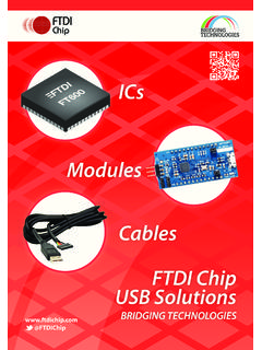
8 The transmitter releases the SDA line (HIGH) during the acknowledge clock pulse. The receiver must pull down the SDA line during the acknowledge clock pulse so that it remains stable LOW during the HIGH period of this clock pulse (see Figure 3). Also, set-up and hold times must also be taken into account. Figure 3 Acknowledge on the I2C-bus Data transfers of I2C specification should follow the format. After the START condition (S), a slave address should be sent first. This address is 7 bits long followed by an eighth bit which is a data direction bit (R/W ) a zero indicates a transmission (WRITE), a one indicates a request for data (READ).
9 After the slave address byte is sent, master can continue its data transfer by writing or reading data byte as defined format. The data transfer is always terminated by a STOP condition generated by the master. 4 Product Page Document Feedback Copyright Future Technology Devices International Limited Application Note AN_113 Interfacing FT2232H Hi-Speed Devices to I2C Bus Version Document Reference No.: FT_000137 Clearance No.: FTDI# 90 2 Sample Project with FT2232H Overview To demonstrate how to use the Multi-Protocol Synchronous Serial Engine (MPSSE) in a USB to I2C bus interface, a sample project is given. An EEPROM (24LC256) device with I2C serial interface is selected as the typical application.
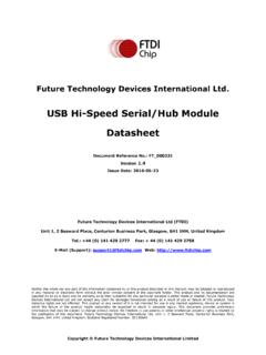
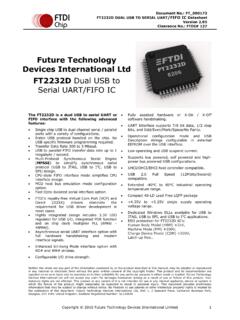
10 A reference schematic showing the I2C connection between the FT2232H and the 24LC256 is given. Additionally some sample software (C++ listing) is provided which illustrates how to initialize, program and read 24LC256 EEPROM device via the I2C interface. Sample Circuit Figure 4 FT2232H interface with 24LC256 Figure 1 illustrates an example of Interfacing the MPSSE port of FT2232H with I2C serial EEPROM device. The FT2232H is in USB bus powered design configuration. Please refer to FT2232H datasheet for detailed specifications. The USB VBus (+5V) is regulated to + to supply VCCIO, VPHY, VPLL and VREGIN of FT2232H , the 93C46 EEPROM and the 24LC256 EEPROM Devices .