Transcription of INTERNATIONAL ISO STANDARD 5457 - Autodesk
1 AReference numberISO 5457:1999(E)INTERNATIONALSTANDARDISO5457 Second edition1999-02-01 Technical product documentation Sizesand layout of drawing sheetsDocumentation technique de produits Formats et pr sentation des l ments graphiques des feuilles de dessinNot for ResaleISO 5457:1999(E) ISO 1999 All rights reserved. Unless otherwise specified, no part of this publication may be reproducedor utilized in any form or by any means, electronic or mechanical, including photocopying andmicrofilm, without permission in writing from the Organization for StandardizationCase postale 56 CH-1211 Gen ve 20 in SwitzerlandiiForewordISO (the INTERNATIONAL Organization for Standardization) is a worldwidefederation of national standards bodies (ISO member bodies).
2 The work ofpreparing INTERNATIONAL Standards is normally carried out through ISOtechnical committees. Each member body interested in a subject for whicha technical committee has been established has the right to be representedon that committee. INTERNATIONAL organizations, governmental and non-governmental, in liaison with ISO, also take part in the work. ISOcollaborates closely with the INTERNATIONAL Electrotechnical Commission(IEC) on all matters of electrotechnical INTERNATIONAL Standards adopted by the technical committees arecirculated to the member bodies for voting.
3 Publication as an InternationalStandard requires approval by at least 75 % of the member bodies castinga STANDARD ISO 5457 was prepared by Technical CommitteeISO/TC 10, Technical drawings, product definition and relateddocumentation, Subcommittee SC 1, Basic second edition cancels and replaces the first edition (ISO 5457:1980),which has been technically A of this INTERNATIONAL STANDARD is for information for Resale--`,,```,,,,````-`-`,,`,,`,`,,`--- INTERNATIONAL STANDARD ISOISO 5457:1999(E)1 Technical product documentation Sizes and layout of drawingsheets1 ScopeThis INTERNATIONAL STANDARD specifies the size and layout of preprinted sheets for technical drawings in any field ofengineering, including those produced by computer.
4 This INTERNATIONAL STANDARD is also applicable to other Normative referencesThe following standards contain provisions which, through reference in this text, constitute provisions of thisInternational STANDARD . At the time of publication, the editions indicated were valid. All standards are subject torevision, and parties to agreements based on this INTERNATIONAL STANDARD are encouraged to investigate thepossibility of applying the most recent editions of the standards indicated below.
5 Members of IEC and ISO maintainregisters of currently valid INTERNATIONAL 128-20:1996, Technical drawings General principles of presentation Part 20: Basic conventions for 216:1975, Writing paper and certain classes of printed matter Trimmed sizes A and B 3098-1:1974, Technical drawings Lettering Part 1: Currently used 7200:1984, Technical drawings Title 9958-1:1992, Draughting media for technical drawings Draughting film with polyester base Part 1:Requirements and markingISO 9961:1992, Draughting media for technical drawings Natural tracing Size of series ISO-AThe original drawing should be made on the smallest sheet permitting the necessary clarity and preferred sizes of the trimmed and untrimmed sheets as well as the drawing space of the main ISO-A series(see ISO 216) are given in table for ResaleISO 5457.
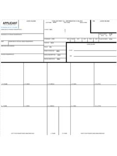
6 1999(E) ISO2 Table 1 Sizes of trimmed and untrimmed sheets and the drawing spaceDimensions in millimetresDesignationFigureTrimmed sheet (T)Drawing spaceUntrimmed sheet (U)a11)b11)a2 0,5b2 0,5a3 2b3 2A018411 1898211 1598801 230A11594841574811625880A214205944005644 50625A31297420277390330450A4221029718027 7240330 NOTE For sizes > A0, see ISO ) For tolerances, see ISO in millimetres Dimensions in millimetres Figure 1 Size A3 to A0 Figure 2 Size A4 The size designation shall be placed in the bottom border at the right corner (see figure 5).
7 Elongated sizesElongated sizes should be avoided. Otherwise they are formed by combination of the dimensions of the short sideof an A-size ( A3) with the dimensions of the long side of another larger A-size ( A1). The result is a newsize, for example with the abbreviation The structure of the size system is shown in figure for Resale ISOISO 5457:1999(E)3 Dimensions in millimetresFigure 3 Size system overview4 Graphical Title blockFor the dimensions and layout of title blocks, see ISO 7200.
8 The location of the title block for the sizes A0 to A3 issituated in the bottom right hand corner of the drawing space. Only sheets positioned horizontally are permitted forthese formats (see figure 1). For the size A4, the title block is situated in the shorter (lower) part of the drawingspace. Only sheets positioned vertically are allowed for this format (see figure 2). The direction of the reading of thedrawings is equal to that of the title Borders and frameBorders enclosed by the edges of the trimmed sheet and the frame limiting the drawing space shall be provided withall sizes.
9 The border shall be 20 mm wide on the left edge, including the frame. It can be used as a filing margin. Allother borders are 10 mm wide (see figure 4).The frame for limiting the drawing space shall be executed with continuous lines of 0,7 mm in millimetresKey1 Trimming mark2 Trimmed format3 Grid reference border4 Frame of drawing space5 Drawing space6 Untrimmed formatFigure 4 BordersNot for ResaleISO 5457:1999(E) Centring marksIn order to facilitate positioning of the drawing when reproduced or microfilmed, four centring marks shall beprovided.
10 These marks are placed at the ends of the two axes of symmetry of the trimmed sheet with a symmetrytolerance of 1 mm. The form of the centring marks may be chosen freely. It is recommended to indicate them bycontinuous lines of 0,7 mm width, starting at the grid reference border and extending 10 mm beyond the drawingframe (see figure 5). Sizes greater than A0 require additional centring marks at the mid-point of each section to Grid reference systemThe sheets shall be divided into fields in order to permit easy location of details, additions, revisions, etc.