Transcription of Introducing the Cisco SNS 3515 and Cisco SNS 3595 …
1 1 Cisco Systems, Introducing the Cisco SNS-3515 and Cisco SNS-3595 Hardware AppliancesThis chapter gives an overview of the Cisco Secure Access Control System ( Cisco SNS-3515 and Cisco SNS-3595) hardware. It covers the appliance hardware, major components, controls, connectors, and front- and rear-panel LED indicators. Product Overview, page 1 LED Indicators on Cisco SNS 3515 and 3595 Appliances, page 5 Regulatory Compliance, page 11 Product OverviewThis section describes the power requirements, rack-mount hardware kit, and features of the Cisco SNS-3515 and Cisco SNS-3595 section contains: Cisco SNS-3515 and Cisco SNS-3595 Appliances Overview, page 1 Cisco SNS-3515 and Cisco SNS-3595 Appliances Hardware Specifications, page 2 Product Serial Number Location, page 4 Cisco Product Identification Tool, page 4 Cisco SNS-3515 and Cisco SNS-3595 Appliances OverviewThe Cisco SNS-3515 or 3595 server is designed for performance and density over a wide range of business workloads, from web serving to distributed on the success of the Cisco SNS-3515 or 3595 server, the enterprise-class Cisco SNS-3515 or 3595 server further extends the capabilities of the Cisco Unified Computing System portfolio in a 1U form factor.
2 The Cisco SNS-3515 server does this with the addition of the Intel Xeon processor E5-2600 product family, which delivers significant performance and efficiency gains. In addition, the Cisco SNS-3515/3595 server offers up to 64GB of RAM, 8 drives, and 2 x 1 GbE lights-out management (LOM) ports that deliver outstanding levels of density and performance in a compact the Cisco SNS-3515 and Cisco SNS-3595 Hardware Appliances Product OverviewCisco SNS-3515 and Cisco SNS-3595 Appliances Hardware SpecificationsTable 1 on page 2describes the hardware specifications of Cisco SNS-3515 and Cisco SNS-3595 : ACS supports an optional redundant power supply unit for Cisco Front ViewFigure 1 on page 3 shows the Cisco SNS-3515 1 Cisco SNS 3515 and Cisco SNS 3595 Hardware SummaryCisco Secure ACS ApplianceHardware SpecificationsDiagramsCisco SNS-3515-ACS-K9 Cisco UCS C220 M4 Single socket Intel Xeon E5-2620 v3 series CPU @ , 6 total cores, 6*2 total threads) 16 GB RAM 1 x 600-GB disk 6 GbE network interfaces For physical, environmental, and power specifications, see Server Specifications, page 4.
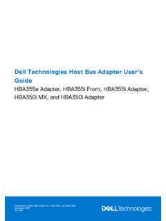
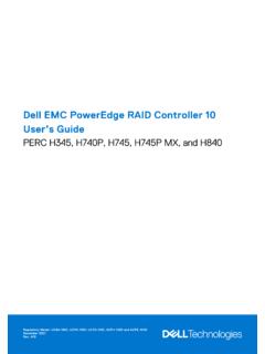
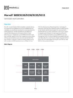
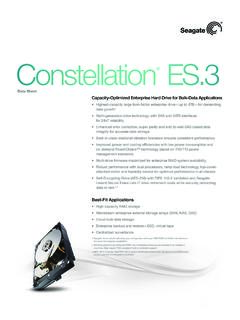
3 Figure 1 on page 3 shows the Cisco SNS-3515 appliance., page 2 Figure 2 Cisco SNS-3515 or 3595 Appliance Rear View, page 3 Cisco SNS-3595-ACS-K9 Cisco UCS C220 M4 Dual socket Intel Xeon E5-2640 v3 series CPU @ , 8 total cores, 8*2 total threads 64 GB RAM 4 x 600-GB disks RAID 10 6 GbE network interfaces For physical, environmental, and power specifications, see Server Specifications, page 4. Figure 1 Cisco SNS-3595/3515 Appliance Front View, page 3 Figure 2 Cisco SNS-3515 or 3595 Appliance Rear View, page 33 Introducing the Cisco SNS-3515 and Cisco SNS-3595 Hardware AppliancesProduct OverviewFigure 1 Cisco SNS-3595/3515 Appliance Front View Chasis Rear ViewFigure 2 on page 3 shows the external features of the Cisco SNS-3515 and Cisco SNS-3595 appliances rear panel. Figure 2 Cisco SNS-3515 or 3595 Appliance Rear View 1 Drives (up to four drives)7 Fan status LED2 Pull-out asset tag8 Temperature status LED3 Operations panel buttons and LEDs9 Power supply status LED4 Power button/power status LED10 Network link activity LED5 Unit identification button/LED11 KVM connector (used with KVM cable that provides two USB , one VGA, and one serial connector)6 System status LEDHDD 02 HDD 01 HDD 03 HDD 0410864157935297411231 Grounding-lug hole (for DC power supplies)10 Serial port (RJ-45 connector)2 PCIe riser 1/slot 111-12 Dual 1-GbE Ethernet ports (LAN1 and LAN2)3 PCIe riser 2/slot 213 VGA video port (DB-15)
4 2456789101112131413154 Introducing the Cisco SNS-3515 and Cisco SNS-3595 Hardware Appliances Product OverviewProduct Serial Number LocationThe serial number label is located at the top of the server near the front panel of the Cisco SNS-3515 or Cisco SNS-3595 appliance, on page 2 shows the location of this label. Cisco Product Identification ToolThe Cisco Product Identification (CPI) tool helps you retrieve the serial number of your Cisco products. Before you submit a request for service online or by phone, use the CPI tool to locate your product serial number. You can access this tool from the Cisco Support website. To access this the Get Tools & Resources the All Tools (A-Z) Cisco Product Identification Tool from the alphabetical drop-down list. This tool offers three search options: Search by product ID or model name. Browse for Cisco model. Copy and paste the output of the show command to identify the product.
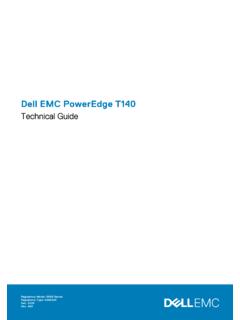
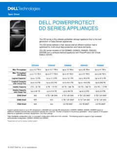
5 Search results show an illustration of your product with the serial number label location highlighted. Locate the serial number label on your product and record the information before you place a service can access the CPI tool at: access the CPI tool, you require a user ID and password. If you have a valid service contract but do not have a user ID or password, you can register at: Component LocationsThis section shows the locations of the field-replaceable components. The view in Figure 1-4 is from the top down with the top cover and air baffle LAN-on-motherboard (mLOM) card slots (4 ports)14 Rear unit identification button/LED8 USB ports (two)15 Power supplies (up to two, redundant as 1+1)91-GbE Ethernet dedicated management port5 Introducing the Cisco SNS-3515 and Cisco SNS-3595 Hardware AppliancesLED Indicators on Cisco SNS 3515 and 3595 AppliancesFigure 3 Replaceable Component LocationsLED Indicators on Cisco SNS 3515 and 3595 AppliancesThis section describes the front- and rear-panel controls, ports, and LED indicators on the Cisco SNS-3515 or Cisco SNS-3595 section contains.
6 Cisco SNS-3515 or 3595 Appliance Front-Panel View, page 61 Drives (SAS/SATA drives are hot-swappable)10 Trusted platform module (TPM) socket on motherboard (not visible in this view)2 Cooling fan modules (six)11 PCIe riser 2 (half-height PCIe slot 2)3 Super cap Power Module (RAID backup) mounting bracket12 PCIe riser 1 (full-height PCIe slot 1)4 DIMM sockets on motherboard (24)13 Modular LOM (mLOM) connector on chassis floor5 CPUs and heat sinks (up to two)14 Cisco modular RAID controller PCIe riser (dedicated riser with horizontal socket)6 Embedded SATA RAID header for RAID 5 key15 Cisco modular RAID controller card7SD card bays on motherboard (two)16 Embedded SATA RAID mini-SAS connectors on motherboard (not visible in this view)8 Internal USB port on motherboard17 RTC battery on motherboard9 Power supplies (up to two, hot-swappable when redundant as 1+1)352978 FAN 6 FAN 5 FAN 4 FAN 3 FAN 2 FAN 1 CPU 2 CPU 1 PSU 2 PSU 1 PCIe Riser 1 PCIe Riser 2SD 1SD 212456789101112131617151436 Introducing the Cisco SNS-3515 and Cisco SNS-3595 Hardware Appliances LED Indicators on Cisco SNS 3515 and 3595 Appliances Cisco SNS-3515 or 3595 Appliance Back-Panel View, page 8 Internal Diagnostic LEDs, page 10 Cisco SNS-3515 or 3595 Appliance Front-Panel ViewFigure 4 on page 6 shows the components of the Cisco SNS-3515 or Cisco SNS-3595 appliance front-panel view.
7 Figure 4 Front Panel LEDs1 Hard drive fault LED6 Fan status LED2 Hard drive activity LED7 Temperature status LED3 Power button/power status LED8 Power supply status LED4 Identification button/LED9 Network link activity LED5 System status LED103530889753468 BAY 02 BAY 01 BAY 03 BAY 04 BAY 05 BAY 06 BAY 08 BAY 07217 Introducing the Cisco SNS-3515 and Cisco SNS-3595 Hardware AppliancesLED Indicators on Cisco SNS 3515 and 3595 AppliancesTable 2 on page 7 describes the LEDs located on the front panel of the Cisco SNS-3515 or Cisco SNS-3595 appliance Table 2 Front-Panel LEDsLED NameStateHard drive faultNote: If your controller is a Cisco UCS RAID SAS 9300-8i or 9300-8e HBA, see Cisco UCS SAS 9300-8i and 9300-8e HBA Considerations for differing LED behavior. Off The hard drive is operating properly. Amber Drive fault detected. Amber, blinking The device is rebuilding. Amber, blinking with one-second interval Drive locate function drive activity Off There is no hard drive in the hard drive tray (no access, no fault).
8 Green The hard drive is ready. Green, blinking The hard drive is reading or writing button/LED Off There is no AC power to the server. Amber The server is in standby power mode. Power is supplied only to the Cisco IMC and some motherboard functions. Green The server is in main power mode. Power is supplied to all server identification Off The unit identification function is not in use. Blue The unit identification function is status Green The server is running in normal operating condition. Green, blinking The server is performing system initialization and memory check. Amber, steady The server is in a degraded operational state. For example: Power supply redundancy is lost. CPUs are mismatched. At least one CPU is faulty. At least one DIMM is faulty. At least one drive in a RAID configuration failed. Amber, blinking The server is in a critical fault state. For example: Boot failed.
9 Fatal CPU and/or bus error is detected. Server is in an over-temperature the Cisco SNS-3515 and Cisco SNS-3595 Hardware Appliances LED Indicators on Cisco SNS 3515 and 3595 AppliancesCisco SNS-3515 or 3595 Appliance Back-Panel ViewFigure 2 on page 3 shows the components of the Cisco SNS-3515 and Cisco 3595 appliance back-panel view. Figure 5 Front Panel LEDsTable 3 on page 9 describes the LEDs located on the front panel of the Cisco SNS-3515 or Cisco SNS-3595 status Green All fan modules are operating properly. Amber, steady One or more fan modules breached the critical threshold. Amber, blinking One or more fan modules breached the non-recoverable status Green The server is operating at normal temperature. Amber, steady One or more temperature sensors breached the critical threshold. Amber, blinking One or more temperature sensors breached the non-recoverable supply status Green All power supplies are operating normally.
10 Amber, steady One or more power supplies are in a degraded operational state. Amber, blinking One or more power supplies are in a critical fault link activity Off The Ethernet link is idle. Green One or more Ethernet LOM ports are link-active, but there is no activity. Green, blinking One or more Ethernet LOM ports are link-active, with 2 Front-Panel LEDs (continued)LED NameState1 Optional mLOM card LEDs (see Table 3 on page 9)51-GbE Ethernet link status LED21-GbE Ethernet dedicated management link status LED6 Rear unit identification button/LED31-GbE Ethernet dedicated management link speed LED7 Power supply status LED41-GbE Ethernet link speed LED353089mLOMPCIe 01 PCIe 02 PSU 01 PSU 021325674129 Introducing the Cisco SNS-3515 and Cisco SNS-3595 Hardware AppliancesLED Indicators on Cisco SNS 3515 and 3595 AppliancesTable 3 Back-Panel LEDsLED NameStateOptional mLOM 1-GbE SFP+ (there is a single status LED) Off No link is present.