Transcription of INTRODUCTION TO AO MODULATORS AND DEFLECTORS
1 INTRODUCTION TO ACOUSTO-OPTIC MODULATORS AND DEFLECTORS : Acousto-optic components are typically used internal or external to laser equipment for the electronic control of the intensity (modulation) and or position (deflection) of the laser beam. Interaction of acoustic waves and light occur in optical materials when the acoustic wave generates a refractive index wave, which acts as a sinusoidal grating in the optical material. An incident laser beam passing through this grating will be diffracted into several orders.
2 With appropriate design of the modulator or deflector and proper adjustment of the incident angle between the laser light and the axis of acoustic propagation in the optical material (Bragg angle), the first order beam can be made to have the highest efficiency. The angle, ( ), the light is diffracted is defined by the equation: aaV f == 2 b (1) Where: is the optical wavelength in air Va is the acoustical velocity of the material fa is the acoustic frequency b is the Bragg angle This is the angle between the incident laser beam and the diffracted laser beam, with the acoustic wave direction propagating at the base of the triangle formed by the three vectors.
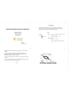
3 A diagram of the relationship between the acoustic wave and the laser beam is shown in figure 1. The intensity of the light diffracted is proportional to the acoustic power (Pa), the figure of merit (M2) of the optical material, electrode geometric factors (L/H) and inversely proportional to the square of the wavelength. )Pa)M)HL( 2( (Sin Eff1/2222= (2) ACOUSTO OPTIC MATERIAL SELECTION A variety of acousto-optical materials are used for Acousto Optic MODULATORS depending on the laser parameters such as wavelength, polarization, and power density.
4 Table 2 is a summary of the properties and figure of merit for most common materials used for the NEOS Technologies acousto optical MODULATORS . For the visible region and near infrared region, the most common MODULATORS are made from dense flint glass, fused Silica, crystal Quartz, Tellurium Dioxide, or chalcogenide glass. At the infrared region, Germanium is the most common material with a relative high figure of merit. Lithium Niobate and Gallium Phosphide are used for high frequency signal processing devices.
5 1 FIGURE 1 OSCILLATORRF AMPAOMINPUTBEAMFOCALPLANEINPUT AOM SYSTEM CONFIGURATIONMIXERFOCUSING LENS WHEN REQUIRED0 ACOUSTO-OPTIC modulator CONSTRUCTION Once the acousto-optic material is selected, it is optically polished. The surfaces of the material that are to be the optical windows are optically AR coated to reduce optical reflections. NEOS uses multi-layer dielectric broadband or V AR coatings on the AO modulator optical windows.
6 Typical losses are from a few percent for external cavity devices to percent for intra-cavity devices. The side of the material that the acoustic energy is to originate from has a Lithium Niobate transducer metal vacuum bonded to the modulator medium. The transducer converts RF energy applied to it into acoustic energy. Metal bonding provides very good acoustic coupling and NEOS uses only high quality metal bonds. Then the transducer is lapped to the fundamental resonant frequency such as 80 MHz.
7 The top surface of the transducer is then metalized with the transducer shape and size defined in this process. The modulator is then tuned to match the electrical impedance of the RF driver, which will supply the RF energy at the frequency of the transducer s resonant frequency.. RF DRIVER CONSTRUCTION The RF driver is typically a fixed frequency oscillator and usually consists of a crystal oscillator, an amplitude modulator with an interface, which accepts input modulation, digital and / or analog, and a RF amplifier, which supplies the AO modulator with the level of RF power needed to achieve the highest diffraction efficiency.
8 The specifications brochures on our web site describe the performance of the modulator and driver systems in detail. 2 DIGITAL MODULATION AND LASER BEAM SHUTTERING An acousto-optic modulator can be used to shutter a laser beam on and off. By applying a digital TTL signal to the modulator s driver digital modulation input, the RF energy applied to the modulator is modulated on and off. To support the on-off signal, the rise time of the modulator system has to follow the digital waveform transition.
9 The limit of the acousto-optic modulator rise and fall time is the transit time of the acoustic wave propagation across the optical beam. The rise time is given by: =tr (3) A typical rise time for a 1 mm diameter laser beam is around 150 nanoseconds. To achieve faster rise times, it is necessary to focus the laser beam through the modulator and decrease the acoustic transit time. A schematic of the focused modulator setup is shown in Figure 1.
10 Since the incident beam is a convergent instead of a collimated beam, the diffraction efficiency decreases as the ratio of the optical beam convergence and the acoustic beam convergence angle increases. For those interested in the design procedure for a wide bandwidth acousto-optic modulator , refer to reference 1. A plot of rise time vs. spot size for three, common AO modulator materials are given in Figure 2. Figure 2 RISE TIME(NANOSECONDS) (MH z)1/e Spot Size (m icrons) modulator Performance2 Fused SilicaTeO2 Flint Glass (SF6) 3 ANALOG MODULATION A acousto-optic modulator has a nonlinear transfer function, and as a result, care must be exercised when applying an analog modulation signal to a acousto-optic modulator .