Transcription of Introduction to Control Systems - Engineering
1 1 1 Introduction to Control Systems In this lecture, we lead you through a study of the basics of Control system. After completing the chapter, you should be able to Describe a general process for designing a Control system. Understand the purpose of Control Engineering Examine examples of Control Systems Understand the principles of modern Control Engineering . Realize few design examples. Textbook 1. Richard C. Dorf and Robert H. Bishop, Modern Control Systems , Prentice Hall, 2001. Introduction Control Engineering is based on the foundations of feedback theory and linear system analysis, and it generates the concepts of network theory and communication theory. Accordingly, Control Engineering is not limited to any Engineering discipline but is applicable to aeronautical, chemical, mechanical, environmental, civil, and electrical Engineering .
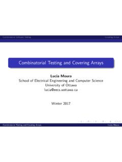
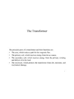
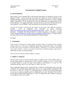
2 A Control system is an interconnection of components forming a system configuration that will provide a desired system response. The basis for analysis of a system is the foundation provided by linear system, which assumes a cause-effect relationship for the components of a system. A component or process to be controlled can be represented by a block as shown in Figure 1. Basic Electronics 2 Figure 1 Process under Control An open-loop Control system utilizes a controller or Control actuator to obtain the desired response as shown in Figure 2. The open-loop Control system utilizes an actuating device to Control the process directly without using device.
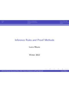
3 An example of an open-loop Control system is an electric toaster. Figure 2 Open-loop Control system (no feedback) A closed-loop Control system (Figure 3) utilizes an additional measure of the actual output to compare the actual output with the desired output response. The measure of the output is called the feedback signal. A feedback Control system is a Control system that tends to maintain a relationship of one system variable to another by comparing functions of these variables and using the difference as a means of Control . As the system is becoming more complex, the interrelationship of many controlled variables may be considered in the Control scheme. An example of closed-loop Control system is a person steering an automobile by looking at the auto s location on the road and making the appropriate adjustments.
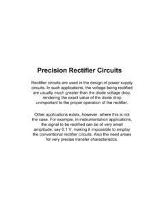
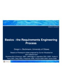
4 Process Output Input Actuating device Process Output Output response Basic Electronics 3 Figure 3 Closed-loop feedback system. TEMPERATURE Control Systems Figure 4 shows a diagram of temperature Control of an electric furnace. The temperature in the electric furnace is measured by a thermometer, which is an analog device. The analog temperature is converted to a digital temperature by an A/D converter. The digital temperature is fed to a controller through an interface. This digital temperature is compared with the programmed input temperature, and if there is any error, the controller sends out a signal to the heater, through an interface, amplifier, and relay, to bring the furnace temperature to a desired value.
5 Figure 4 Temperature Control system. A/D Converter Interface Relay Amplifier InterfaceThermometer I NP UT ControllerProcessMeasurement DeviceDifference or Actuating Error Desired Output Response Actual Output Response Basic Electronics 4 Control SYSTEM DESIGN The following table shows the Control system design process. Variables to Control are the quantities or conditions that are measured and controlled. Process is a natural, progressively continuing operation marked by a series of gradual changes that succeed one another in a relatively fixed way and lead toward certain result or end.
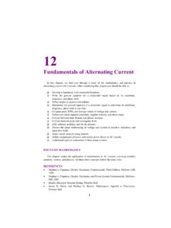
6 A system is a combination of components that act together and perform a certain objective. 1. Establish Control goals 2. Identify the variables to Control 3. Write the specifications for the variables 4. Establish the system configuration and identify the actuators 5. Obtain a model of the process, the actuator, and the sensor 6. Describe a controller and select key parameters to be adjusted 7. Optimize the parameters and analyze the performance Basic Electronics 5 DESIGN EXAMPLE: TURNABLE SPEED Control Figure 5 Open-loop Control of speed of a turntable and a block diagram model.
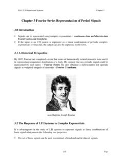
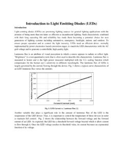
7 Figure 6 Closed-loop Control of the speed of a turntable. Control Device (Amplifier) Actuator (DC Motor) Process (Turntable) Desired Speed Battery DC AmplifierTurntableDC Motor Battery DC AmplifierTurntableDC Motor TachometerActual Speed Basic Electronics 6 DESIGN EXAMPLE: DISK DRIVE READ SYSTEM Figure 7 Closed-loop Control system for disk drive. A hard disk uses round, flat disks called platters, coated on both sides with a special media material designed to store information in the form of magnetic patterns. The platters are mounted by cutting a hole in the center and stacking them onto a spindle.
8 The platters rotate at high speed, driven by a special spindle motor connected to the spindle. Special electromagnetic read/write devices called heads are mounted onto sliders and used to either record information onto the disk or read information from it. The sliders are mounted onto arms, all of which are mechanically connected into a single assembly and positioned over the surface of the disk by a device called an actuator. A logic board controls the activity of the other components and communicates with the rest of the computer. For details see Figure 8 and Figure 9. Control Device Actuator and Read Arm Sensor Error Desired Head Position Actual Head Position Basic Electronics 7 Figure 8 A hard disk.
9 Basic Electronics 8 Figure 9 Components of a hard disk Basic Electronics 9 FEEDBACK Control OF AN ANTIAIRCRAFT GUN Figure 10 Feedback Control of an antiaircraft system. Control System Gun Dynamics Gun Azimuth (Elevation) Demanded Azimuth (Elevation) Basic Electronics 10 Exercises A precise optical signal source can Control the output power level to within 1%.
10 A laser is controlled by an input current to yield the output power. A microprocessor controls the input current to the laser. The microprocessor compares the desired power level with a measured signal proportional to the laser power output obtained from a sensor. Draw the block diagram representing the closed-loop Control system. Micro processorLaser (Process) Sensor (Measurement) Measured power Desired Power output CurrentErrorOutput power Basic Electronics 11 Automated highways may be prevalent in the next decade.