Transcription of Introduction to Electrical Design for Cathodic Protection ...
1 Introduction to Electrical Design for Cathodic Protection Systems Ezekiel Enterprises, LLC Introduction to Electrical Design for Cathodic Protection Systems Course# EE410 Ezekiel Enterprises, LLC 301 Mission Dr. Unit 571 New Smyrna Beach, FL 32128 386-882-EZCE(3923) Updated - Oct 2015 Introduction to Electrical Design for Cathodic Protection Systems Ezekiel Enterprises, LLC Table of Contents 1. Introduction TO Cathodic Protection .. 2 Purpose.. 2 Corrosion.. 2 Cathodic 2 Types of Cathodic Protection systems.. 3 2. Cathodic Protection Design .. 4 Required information.. 4 Determining type and Design of Cathodic Protection system.
2 7 3. CURRECT REQUIREMENT TESTING .. 16 Required current.. 16 Sample test.. 16 4. EXAMPLES OF GALVANIC Cathodic Protection Design .. 17 Underground steel storage tank.. 17 Gas distribution system.. 18 5. EXAMPLES OF IMPRESSED CURRENT Cathodic Protection Design .. 21 Steel gas main.. 21 Heating distribution system.. 25 REFERENCES .. 29 1 | Page Oct 2015 Introduction to Electrical Design for Cathodic Protection Systems Ezekiel Enterprises, LLC Introduction TO Electrical Design FOR Cathodic Protection SYSTEMS 1. Introduction TO Cathodic Protection Purpose. This course presents Design guidance for Cathodic Protection systems. Corrosion. Corrosion is an electrochemical process in which a current leaves a structure at the anode site, passes through an electrolyte, and re-enters the structure at the cathode site.
3 For example, one small section of a pipeline may be anodic (positively charged) because it is in a soil with low resistivity compared to the rest of the line. Current would leave the pipeline at that anode site, pass through the soil, and re-enter the pipeline at a cathode (negatively charged) site. Current flows because of a potential difference between the anode and cathode. That is, the anode potential is more negative than the cathode potential, and this difference is the driving force for the corrosion current. The total system - anode, cathode, electrolyte, and metallic connection between anode and cathode is termed a corrosion cell. (the pipeline in fig 1-1 is termed a corrosion cell. Figure 1-1 Cathodic Protection . Cathodic Protection is a method to reduce corrosion by minimizing the difference in potential between anode and cathode.)
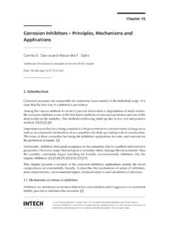
4 This is achieved by applying a current to the structure to be protected (such as a pipeline) from some outside source. When enough current is applied, the whole structure will be at one potential; thus, anode and cathode sites will not exist. Cathodic Protection is commonly used on many types of structures, such as pipelines, underground storage tanks, locks, and ship hulls. 2 | Page Oct 2015 Introduction to Electrical Design for Cathodic Protection Systems Ezekiel Enterprises, LLC Types of Cathodic Protection systems. There are two main types of Cathodic Protection systems: galvanic and impressed current. Figure 1-2 shows these two types. Note that both types have anodes (from which current flows into the electrolyte), a continuous electrolyte from the anode to the protected structure, and an external metallic connection (wire).
5 These items are essential for all Cathodic Protection systems. Figure 1-2 Galvanic (a) and impressed (b) current systems for Cathodic Protection a. Galvanic system. A galvanic Cathodic Protection system makes use of the corrosive potentials for different metals. Without Cathodic Protection , one area of the structure exists at a more negative potential than another, and corrosion results. If, however, a much less inert object (that is, with much more negative potential, such as a magnesium anode) is placed adjacent to the structure to be protected, such as a pipeline, and a metallic connection (insulated wire) is installed between the object and the structure, the object will become the anode and the entire structure will become the cathode.
6 That is, the new object corrodes sacrificially to protect the structure as shown in Figure 1-2 (a). Thus, the galvanic cathode Protection system is called a sacrificial anode Cathodic Protection system because the anode corrodes sacrificially to protect the structure. Galvanic anodes are usually made of either magnesium or zinc because of these metals higher potential compared to steel structures. b. Impressed current systems. Impressed current Cathodic Protection systems use the same elements as the galvanic Protection system, only the structure is protected by applying a current to it from an anode. The anode and the structure are connected by an insulated wire, as for the galvanic system. Current flows from the anode through the electrolyte onto the structure, just as in the galvanic system.
7 The main difference between galvanic and impressed current systems is that the galvanic system relies on the difference in potential between the anode and the structure, whereas the impressed current system uses an external power source to drive the current, as shown in Figure 1-2 (b). The external power source is usually a rectifier that changes input AC power to the proper DC power level. The rectifier can be adjusted so that proper output can be maintained during the system s life. Impressed current Cathodic Protection system anodes typically are high-silicone cast iron or graphite. 3 | Page Oct 2015 Introduction to Electrical Design for Cathodic Protection Systems Ezekiel Enterprises, LLC Figure 1-2 2.
8 Cathodic Protection Design Required information. Before deciding which type, galvanic or impressed current, Cathodic Protection system will be used and before the system is designed, certain preliminary data must be gathered. a. Physical dimensions of structure to be protected. One important element in designing a Cathodic Protection system is the structure's physical dimensions (for example, length, width, height, and diameter). These data are used to calculate the surface area to be protected. b. Drawing of structure to be protected. The installation drawings must include sizes, shapes, material type, and locations of parts of the structure to be protected. c. Electrical isolation. If a structure is to be protected by the Cathodic system, it must be electrically connected to the anode, as Figure 1 shows.
9 Sometimes parts of a structure or system are electrically isolated from each other by insulators. For example, in a gas pipeline distribution system, the inlet pipe to each building might contain an electric insulator to isolate in-house piping from the pipeline. Also, an Electrical insulator might 4 | Page Oct 2015 Introduction to Electrical Design for Cathodic Protection Systems Ezekiel Enterprises, LLC be used at a valve along the pipeline to electrically isolate one section of the system from another. Since each electrically isolated part of a structure would need its own Cathodic Protection , the locations of these insulators must be determined. d. Short circuits. All short circuits must be eliminated from existing and new Cathodic Protection systems.
10 A short circuit can occur when one pipe system contacts another, causing interference with the Cathodic Protection system. When updating existing systems, eliminating short circuits would be a necessary first step. e. Corrosion history of structures in the area. Studying the corrosion history in the area can prove very helpful when designing a Cathodic Protection system. The study should reinforce predictions for corrosivity of a given structure and its environment; in addition, it may reveal abnormal conditions not otherwise suspected. Facilities personnel can be a good source of information for corrosion history. f. Electrolyte resistivity survey. A structure's corrosion rate is proportional to the electrolyte resistivity. Without Cathodic Protection , as electrolyte resistivity decreases, more current is allowed to flow from the structure into the electrolyte; thus, the structure corrodes more rapidly.