Transcription of Introduction to Microstrip Antennas - University of Houston
1 Introduction to Microstrip AntennasDavid R. JacksonDept. of ECEU niversity of Houston1 David R. JacksonDept. of ECEN308 Engineering Building 1 University of HoustonHouston, TX 77204-4005 Phone: 713-743-4426 Fax: 713-743-4444 Email: InformationPurpose of Short Course Provide an Introduction to Microstrip Antennas . Provide a physical and mathematical basis for understanding how Microstrip Antennas work. Provide a physical understanding of the basic physical properties of Microstrip Antennas . Provide an overview of some of the recent advances and trends in the area (but not an exhaustive survey directed towards understanding the fundamental principles).
2 3 Additional Resources Some basic references are provided at the end of these viewgraphs. You are welcome to visit a website that goes along with a course at the University of Houston on Microstrip Antennas (PowerPoint viewgraphs from the course may be found there, along with the viewgraphs from this short course).4 ECE 6345: Microstrip :You are welcome to use anything that you find on this website, as long as you please acknowledge the Overview of Microstrip Antennas Feeding methods Basic principles of operation General characteristics CAD Formulas Input Impedance Radiation pattern Circular polarization Circular patch Improving bandwidth Miniaturization Reducing surface waves and lateral radiation5 Notation600002/k ==10rkk =[ ] = 0/cf =[ ] 10m/sc= 10/r =[][ ]
3 0070120201410 10F/mcc == = c=speed of light in free space0 =wavelength of free space0k=wavenumber of free space1k=wavenumber of substrate0 =intrinsic impedance of free space1 =intrinsic impedance of substrater =relative permtitivity (dielectric constant) of substrateeffr =effective relative permtitivity (accouting for fringing of flux lines at edges)effrc =complex effective relative permtitivity (used in the cavity model to account for all losses)Outline Overview of Microstrip Antennas Feeding methods Basic principles of operation General characteristics CAD Formulas Input Impedance Radiation pattern Circular polarization Circular patch Improving bandwidth Miniaturization Reducing surface waves and lateral radiation7 Overview of Microstrip AntennasAlso called patch Antennas One of the most useful Antennas at microwave frequencies (f> 1 GHz).
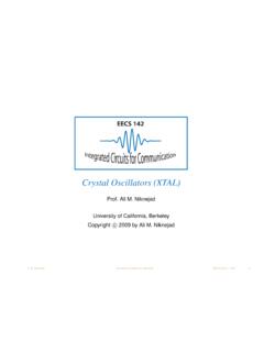
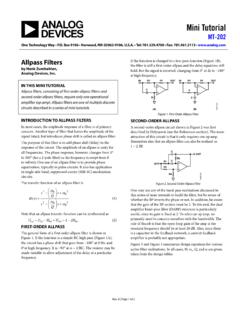
4 It usually consists of a metal patch on top of a grounded dielectric substrate. The patch may be in a variety of shapes, but rectangular and circular are the most common. 8 Microstrip line feedCoax feedOverview of Microstrip Antennas9 Common ShapesRectangularSquareCircularElliptica lAnnular ringTriangular Invented by Bob Munson in 1972 (but earlier work by Dechampsgoes back to 1953). Became popular starting in the Deschampsa n d W. Sichak, Microstrip Microwave Antennas , Proc. of Third Symp. on USAF Antenna Research and Development Program, October 18 22, E.
5 Munson, Microstrip Phased Array Antennas , Proc. of Twenty-Second Symp. on USAF Antenna Research and Development Program,October E. Munson, Conformal Microstrip Antennas and Microstrip Phased Arrays, IEEE Trans. Antennas Propagat., vol. AP-22, no. 1 (January 1974): 74 of Microstrip AntennasHistoryAdvantages of Microstrip Antennas Low profile (can even be conformal, flexible to conform to a surface). Easy to fabricate (use etching and photolithography). Easy to feed (coaxial cable, Microstrip line, etc.). Easy to incorporate with other Microstrip circuit elements and integrate into systems.
6 Patterns are somewhat hemispherical, with a moderate directivity (about 6-8 dBis typical). Easy to use in an array to increase the of Microstrip AntennasDisadvantages of Microstrip Antennas Low bandwidth (but can be improved by a variety of techniques). Bandwidths of a few percentare typical. Bandwidth is roughly proportional to the substrate thickness and inversely proportional to the substrate permittivity. Efficiency may be lower than with other Antennas . Efficiency is limited by conductor and dielectric losses*, and by surface-wave loss**.
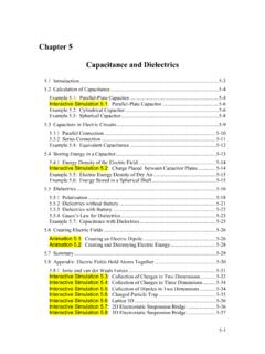
7 Only used at microwave frequencies and above (the substrate becomes too large at lower frequencies). Cannot handle extremely large amounts of power (dielectric breakdown).* Conductor and dielectric losses become more severe for thinner substrates.** Surface-wave losses become more severe for thicker substrates (unless air or foam is used).12 Overview of Microstrip AntennasApplications Satellite communications Microwave communications Cell phone Antennas GPS antennas13 Applications include:Overview of Microstrip AntennasMicrostrip Antenna Integrated into a System: HIC Antenna Base-Station for 28-43 GHzFilterDiplexerLNAPDK-connectorDC supply Micro-D connectorMicrostrip antennaFiber input with collimating lens(Photo courtesy of Dr.)
8 Rodney B. Waterhouse)14 Overview of Microstrip AntennasOverview of Microstrip Antennas15 ArraysLinear array (1-D corporate feed)2 2 array2- D 8X8 corporate-fed array4 8 corporate-fed / series-fed arrayWraparound Array (conformal)(Photo courtesy of Dr. Rodney B. Waterhouse)16 Overview of Microstrip AntennasThe substrate is so thin that it can be bent to conform to the :Lis the resonant dimension (direction of current flow). The width Wis usually chosen to be larger than L(to get higher bandwidth). However, usually W< 2L (to avoid problems with the (0,2) mode).
9 17 Overview of Microstrip AntennasRectangular patchW= rJsNote:The fields and current are approximately independent of yfor the dominant (1,0) Patchxyha r18 Overview of Microstrip AntennasThe location of the feed determines the direction of current flow and hence the polarization of the radiated Overview of Microstrip Antennas Feeding methods Basic principles of operation General characteristics CAD Formulas Input Impedance Radiation pattern Circular polarization Circular patch Improving bandwidth Miniaturization Reducing surface waves and lateral radiation19 Feeding MethodsSome of the more common methods for feeding Microstrip Antennas are
10 Feeding methods are illustrated for a rectangular patch,but the principles apply for circular and other shapes as FeedNote:A feed along the centerline at y= W/2is the most common(this minimizes higher-order modes and cross-pol).xyLWFeed at (x0, y0)Surface current21xr hzFeeding Methods22 Advantages: Simple Directly compatible with coaxial cables Easy to obtain input match by adjusting feed positionDisadvantages: Significant probe (feed) radiation for thicker substrates Significant probe inductance for thicker substrates (limits bandwidth) Not easily compatible with arraysCoaxial Feed20cosedgexRRL = xr hzFeeding MethodsxyLW()00,xy(The resistance varies as the square of the modal field shape.)