Transcription of Introduction to Modbus Serial and Modbus TCP
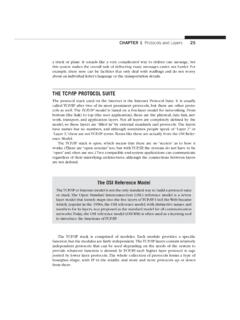
1 Table 1. Modbus over Serial Line uses a three-layer 1. A slave address field and error check wrap around a Modbus 2. RTU framing is more condensed than ASCII (No part of the Extension may be reproduced without the written consent of Contemporary Controls.)Volume9 Issue5 SEPTEMBER OCTOBER 2008 2008 Contemporary Control Systems, George Thomas, Contemporary ControlsIn this second part of a two-partseries on Modbus , we will discusstwo implementations of the ModbusProtocol that were introduced in ourprevious article. The first implemen-tation is the traditional implementa-tion of Modbus over a Serial second implementation is moremodern with Modbus operating overa TCP/IP network.
2 Both implementa-tions remain over Serial has released a Modbusover Serial Line Specification andImplementation Guide provides guidance when usingModbus with Serial links. As mentioned in our previous article, Modbus was originally intended tobe used with point-to-point EIA-232 Cinterfaces with the master being aHuman Machine Interface (HMI) anda PLC as the slave. Multiple slavesconnected to one master would thenrequire multiple links which isinconvenient and expensive. Itwould be only natural to change thepoint-to-point link to a multipointserial infrastructure such as EIA-485which would allow one master tocommunicate to multiple slaves overa common Serial line.
3 This approachis encouraged in the , but not mentioned in theoriginal Modicon Modbus ProtocolReference Layer ModelInstead of the traditional seven-layerISO Open Systems InterconnectionReference Model, the Modbus overSerial Line model is collapsed tothree layers as shown in Table 1. Atthe top is the application layer thatwas discussed in part 1. This iscalled the Modbus ApplicationProtocol or simply the ModbusProtocol. Layers 3 6 are not used instead, the model relies on theapplication layer to ensure end-to-end delivery of a message. The datalink (layer 2) is occupied by theModbus Serial Line protocol .
4 Finally,the physical layer (layer 1) allows for either the EIA-232C or EIA-485implementation. With only three layers, Modbus over Serial Line iseasier to understand than otherindustrial protocols. Since theModbus Application protocol wasdiscussed in part 1, it will not berepeated here. Instead, only the data link and physical layers will be discussed. Data Link LayerMuch about the Modbus over SerialLine protocol Data Unit (PDU) wasmentioned in part 1 but will be summarized below. Referring toFigure 1, note that the PDU consistsof four elements. In the middle isthe Modbus PDU consisting of afunction code and data.
5 MostModbus implementations only use asubset of all the available functioncodes. The data structure maychange depending upon the functioncode. Wrapping the Modbus PDU isan address field and an error checkfield. The address field only containsslave addresses or the broadcastaddress. The master address is notrequired and not referenced sincethis is a master/slave protocol withcommands originating from a unique mentioned in part 1, the actualframing of Modbus over Serial Linemessages depends on whether ASCIIor RTU transmission mode is is the most popular mode andis shown in Figure 2.
6 It is a verycompact frame with only one bytereserved for the slave or broadcastaddress, one byte for the functioncode and two bytes for the CRCerror check. A single byte carries thefunction code. Notice that there is no end-of-frame sequence. WithRTU, end-of-frame is indicated character times of silence. Introduction to Modbus Serial and Modbus TCP2 The largest frame occupies only 256bytes. With RTU each byte is sentusing 11 bits. Each data characterrequires eight bits. There is one start-bit, one stop-bit and one parity-bit. Ifparity is not used, another stop-bit issent in its place.
7 If parity is employed,it can be odd or ASCII message format in Figure3 requires two bytes for the slaveaddress as well as for the functioncode. Unlike RTU, the ASCII frameuses a two-byte LRC for the errorcheck field. The advantage of theASCII format is that it is human readable. Notice that there is an end-of-frame sequence composed of carriage return and line feed (CR,LF).Inter-frame spacing is not is represented as a hexadecimalvalue coded as ASCII. Therefore,only 7 bits are required for everyASCII character, but two charactersare required for each byte of start-bit and one stop-bit areused.
8 If a parity-bit is used, eitherodd or even parity can be sent. If noparity is sent, then another stop-bit issent. This means each byte in ASCIIis sent as 10 bits. Physical Layer The original Modbus protocol calledfor a point-to-point EIA-232C linkbetween a host computer and a option remains today. But theModbus over Serial Line specificationencourages the use of the multipointEIA-485 standard supporting upto 32 devices over a common can be implemented with eithera two-wire or four-wire cabling configuration. With any of the serialline implementations, a wide rangeof baud rates from kbps to 115kbps are allowed, but all implemen-tations must at least support kbpsand kbps.
9 The default rate NetworkFigure 4 shows a recommended two-wire interface for EIA-485 networkswith applied line polarization. Asexpected, there is one master trans-ceiver and multiple slave transceiversconnected to a common 2-wire buswith the wires labeled D1 and D0. At a minimum, a total of 32 devicesmust be supported. With a 2-wirebus, the output of the transmitter isdirectly tied to the input of a receiverat each device. Even though this iscalled a 2-wire bus, there is a common reference connectionlabeled common. Each device mustshare its common with all otherdevices on the bus to ensure that themaximum common-mode voltagerating of the device is not line polarization network (consisting of a pull-up and pull-down resistor) is shown near themaster, but its location is not arequirement only a polarization is used to force thebus into a known state when nodrivers are active.
10 EIA-485 receiversrequire a 200 mv failsafe bias toensure they detect a floating line asan off state. This is why line polarization is typically referred to asfailsafe bias. At each end of the busare line terminators (LT) to matchthe natural impedance of the pull-up and pull-down resistors interact with the two terminationresistors to create the failsafe Modbus over Serial Line specification recommends that thepull-up and pull-down resistors havevalues between 450 and 650 ohms,and that only one network is assumes that failsafe bias isneeded at all.