Transcription of Introduction to Railroad Track Structural Design
1 BCR2A 09 Railroad Track Design Including Asphalt Trackbeds Pre-Conference WorkshopIntroduction to Railroad Track Structural DesignDon Uzarski, , Vertical Load Distribution, and DeflectionsComponents do not function independently!Each component layer must protect the one Distribution3 Deflection ProfileSource: Selig and Waters, Track Geotechnology and Substructure Management, 19944 Static vs. Dynamic Loads Dynamic loads higher Acceleration from speed Downward rotation of wheel Smaller wheels, faster rotation, more acceleration Speed/wheel influence Pv= P + P (AREMA)wherePv= Vertical Dynamic Load (lbs) = D33x VDwx 100D = Wheel diameter (in)V = Speed (MPH)P = Static Load (lbs) Larger wheels impose less influence Additional dynamic loads from impacts such as caused by wheel flat spots, rail discontinuities ( frog flangeways), Track transitions ( bridge approaches), Track condition, Wheel Diameters38 inches28 inches36 inches33 inches36 inches6 Track Stiffness Rail is assumed to be a beam on an elastic foundation Modulus of Track Elasticity, u (or k) ( Track Modulus)u = P/ whereu = Modulus of Track Elasticity (lbs/in/in)
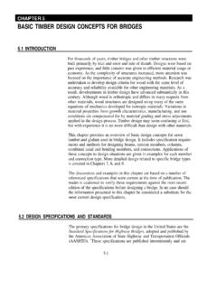
2 P = Wheel load per unit length of rail (lbs/in) = Unit of Track Deflection (in), less play or Track looseness oru = P/Swhereu = Modulus of Track Elasticity (lb/in/in)P = Wheel load (lbs) required to deflect the Track 1 inch on one tieS = Tie spacing (in)7 Classic Approach to Track Analysis and Design Continuously supported beam Notes: a = tie spacing s w(x) = deflection y Source: Kerr, , Fundamentals of Railway Track Engineering, 20038 Talbot equationsRail Moment: Mo= :Yo= Seat Load:Qo= (Note: Fmax) where:P = Wheel Load (lbs)u = Track Modulus (lbs/in/in)S = Tie spacing (in)x1= ( /4)(4EI/u) (in)EI = Flexural rigidity of railwith:E = Modulus of Elasticity of Rail (30x106psi)I = Rail Moment of Inertia (in4)9 Master DiagramSource: Hay, , Railroad Engineering, 198210 Load Deflections and Bending MomentsSource: Hay, , Railroad Engineering, 198211 Determination of Rail Seat Forces (Q or F)Pressure p(x)[lb/in] CurveSource: Kerr, , Fundamentals of Railway Track Engineering, 200312 Pressure Distribution vs.
3 Track ModulusSource: Kerr, , Fundamentals of Railway Track Engineering, 200313 Pressure Distribution vs. Rail WeightSource: Kerr, , Fundamentals of Railway Track Engineering, 200314 Relationship Between Fmax(Qo) and PSource: Kerr, , Fundamentals of Railway Track Engineering, 200315 Maximum Rail Moment and Rail Seat Force LocationsMaximum Rail Seat Force LocationsMaximum Rail Bending Moment Locations16 Design Steps (AREMA, DoD, and Others)(Generalized) Design wheel load based on most common, heaviest car and desired Track speed. Consider all wheels in a truck and proximity of adjacent a Track Modulus, u or k, based on desired Design rail size and moment and loading rail bending trial tie spacing and calculate maximum rail seat load17 Design Steps (con t) tie tie bending and select plate size based on minimum ballast surface ballast depth based on allowable subgrade Track deflection under load and check on deflection is unacceptable, re-do Design Always consider economics!
4 18 Track Deflection vs. Track PerformanceSource: Hay, , Railroad Engineering, 198219 Track Modulus, u or k, Typical Values Well maintained wood tie Track , 3000 lb/in/in Concrete tie Track , 6000 lb/in/in Wood tie Track after tamping, 1000 lb/in/in Wood tie Track with frozen ballast/subgrade, 9000 lb/in/in Track on Ballasted Concrete Bridge Deck, 8000 to 12000 lb/in/inModulus higher during excessively dry periods and lower when subgrade at or near Analysis and Design (weight and section selection) Many rail weights and sections have evolved by the efforts of various designers American Railway Association (ARA) forerunner to Association of American Railroads (AAR) {branded RA or RB on rail} American Society of Civil Engineers (ASCE) {branded AS} American Railway Engineering and Maintenance of Way Association (AREMA) (formerly American Railway Engineering Association (AREA)) {branded RE} International Union of Railways {branded UIC} Railroads (many designations)Note: Sometimes numbers, not letters, are used to denote sections.
5 Depends on Bending stressS = Moc/I or S = Mo/ZwhereS = Bending stress, psiMo= Max bending moment, in-lbsc = Distance to base from neutral axis, inI = Moment of inertia of rail, in4Z = Section modulus, I/c (properties of rail section) allowable bending stress, typically is: 32,000 psi for jointed rail 25,000 psi for continuously welded rail (CWR)22 Maximum bending moment, MoMo= P(EI/64u)1/4 (Mo= )whereMo= Max bending momentP = Max wheel load, lbs (static or dynamic)E = Modulus of elasticity = 30 x 106psiI = Moment of inertia, in4u = Track modulus, lbs/in/inNote: Must account for moments from adjacent wheels. Compute from Master Diagram, computer code, or EXCEL. I and c are a function of Design Greater weight -greater I Increase height -greater I (limiting factor is web height -thickness ratio) Must keep maximum bending stress less than or equal to allowable bending stress23 IcZ = I/cSource: Hay, , Railroad Engineering, 198224 Tie Analysis and Design (size and spacing) Action under load Early belief that tie reaction was uniform Not so, Talbot found that stress concentrated under rail seatSource: Hay, , Railroad Engineering, 198225 Theoretical Design Force diagram (close to center-bound condition) Look at bending moments under center and rail seat Mc= (Qo/4)(L1-2L2) Mr= -QoL22/LTiePPL1L2L2wL1/2 McwMrwL = L1+ 2L2Qo(Fmax)QoQoQomust account for adjacent wheels.
6 Recall, pressure distribution and principle of (Fmax)26 Maximum allowable bending moment Simple beam momentS = Mc/IorM = SI/cwhere M = bending moment, inch-lbsI = moment of inertia = bh3/12, in4c = dist from base to neutral axis = h/2, inchesS = allowable wood fiber bending stress, lb/in2h = tie height, inchesb = tie width, inchesthenM = (bh3S/12)/(h/2) = bh2S/6 S varies by wood specie ( , 1000 psi for shortleaf yellow pine, 1200 psi for longleaf yellow pine, 900 psi for douglas fir, and 1400 psi for oak)27 Optimal tie lengthSource: Hay, , Railroad Engineering, 198228 Practical Design Load distribution Bearing area is of tie length (tamping zone), soA'b= Lband unit load on ballast will bepa= 2Qo/A bthuspa= 3Qo/Lbwherepa= unit tie pressure on ballast (<65 psi wood, <85 psi concrete)A'b= total tie bearing area, in2L = tie length, inchesb = tie width, inchesQo= Rail seat load, lbs (static or dynamic), based on trial tie spacing29 Two basic types Single shoulder Double shoulder Size Width sized to fit tie Length to keep stress on wood tie <200 psi Stress = Qo/Plate Area Limited set of fixed sizes (generally choose smallest size possible for economics)
7 Distance between shoulders (double shouldered plates) spaced to match rail base widthPlate Analysis and Design (size selection)30 Ballast Analysis and Design (depth determination)Source: AREMA, Manual for Railway Engineering, Chapter 16, 200031 Gaussian Distribution Curves and Subgrade PressureSource: Hay, , Railroad Engineering, 1982 QoQo32 Ballast depth (ballast and subballast combined) = f(applied stress, tie reaction, and allowable subgrade stress) Talbot Equationh = ( )4/5whereh = Support ballast depthpa= Stress at bottom of tie (top of ballast) pc= allowable subgrade stressNote: Stress distribution independent of material Japanese National Railways Equationpc= 50pa/(10+ ) Boussinesq Equationpc= 6P/2h2where P = wheel load (lbs) Love s Formulapc= pa{1-[1/(1+r2/h2)]3/2}where r = Radius of a loaded circle whose area equals the effective tie bearing area under one rail 33 Ballast vs.
8 Subballast New construction or reconstruction Generally, half of overall ballast depth should be highest quality available 6 minimum depth for subballast (AREMA) Railroads may have own minimums ( CN requires 12 ) Existing Track All or some of the old ballast layer becomes new subballast layer when new ballast is added, but old material likely to be of marginal quality and layer function may be compromised Bottom ballast and subballast differentiation becomes blurred Ballast layer often described as having a top ballast section and bottom ballast section. The top ballast section encompasses the tamping "Traditional" Design value of 20 psi AREMA recommends limiting stress to 25 psi Using soil strength with a factor of safety-AREMA recommends a factor of safety of at least 2 and as much as 5 or more depending on the traffic (wheel loads and load repetitions) and soil Design standards will dictate ( Army allows a Design unconfined compressive strength (qu) of qu for "normal" traffic levels -less than 5 MGT/yr -and Design of quwhen traffic levels exceed 5 MGT.)
9 -Hay recommends factor of safety of as applied to an ultimate bearing capacity of < qu, thus allowable stress < allowable Stress (Pressure)35 allowable Subgrade Bearing PressuresSource: Selig and Waters, Track Geotechnology and Substructure Management, 199436 Design Standards, Criteria, and Approaches Many railroads (including railroads) have established Design standards and/or criteria Differences do exist between railroads. Examples include: Some use of wood tie length in analyses; some use entire length Some use entire concrete tie length in analyses; some use length Some use a rail seat force of Qox allowable bending stress in rail may vary allowable rail seat load for determining plate size may vary. Depends on wood specie. Range about 250 400 psi.
10 (AREMA recommends 200 psi).37 Differences (con t) AREMA recommends a tie reaction of 65 lbs/in2under wood ties and 85 lbs/in2under concrete ties, but some railroads use the same for both ( 75 lbs/in2) Stiffer Track Higher loads! Why these values? Ballast quality and ability to resist crushing forces (ballast degradation is the number 1 cause of ballast fouling) Some railroads use different Track modulus (u) values in Design . For example, Spring u may be used for rail bending and ballast depth, but Winter u used for rail seat forces. Other railroads may use a single u value . 38 Canadian National Example39CN SPC 1301 Table 1 (con t)40 BNSF Standard Cross Section41 Design approach is part science, part art Track modulus is neither constant nor precise Relationship between Track deflection and performance not exact Assumed Gaussian pressure distribution not entirely correct The challenge is in determining allowable ballast and subgrade stresses Design approach is not robust Ballast and subgrade properties not adequately considered Tonnage (MGT)