Transcription of INTRODUCTION TO TRANSMISSION SYSTEM
1 INTRODUCTION TO TRANSMISSION SYSTEM :- TYPES OF TRANSMISSION SYSTEM CLUTCH GEAR BOX PROPEELER SHAFT UNIVERSAL JOINTS Final drive and differential REAR AXLE Definition Of TRANSMISSION SYSTEM :- The mechanism that transmits the power developed by the engine of automobile to the engine to the driving wheels is called the TRANSMISSION SYSTEM (or POWER TRAIN).It is composed of Clutch The gear box Propeller shaft Universal joints Rear axle Wheel Tyres requirements Of TRANSMISSION SYSTEM :- Provide means of connection and disconnection of engine with rest of power train without shock and smoothly. Provide a varied leverage between the engine and the drive wheels Provide means to transfer power in opposite direction. Enable power TRANSMISSION at varied angles and varied lengths.
2 Enable speed reduction between engine and the drive wheels in the ratio of 5:1. Enable diversion of power flow at right angles. Provide means to drive the driving wheels at different speeds when required. Bear the effect of torque reaction , driving thrust and braking effort effectively. The above requirements are fulfilled by the following main units of TRANSMISSION SYSTEM :- Clutch Gear Box Transfer Case Propeller Shaft and Universal Joints. Final Drive Differential Torque Tube Road Wheel Difference between tyre and wheel :- Wheel Tyre A wheel is a device that allows heavy objects to be moved easily through rotating on an axle through its centre, facilitating movement or transportation while supporting a load (mass),or performing labor in machine.
3 While tyre is the outer part of the wheel made up with rubber and mostly use in vehicles for smooth movement Types Of TRANSMISSION SYSTEM -: Hydraulic TRANSMISSION SYSTEM :- Fluid coupling -: A fluid coupling is a hydrodynamic device used to transmit rotating mechanical has been used in automobile transmissions as an alternative to a mechanical clutch. How fluid coupling can be act as a mechanical clutch ? oIn automotive applications, the pump typically is connected to the flywheel of the engine The turbine is connected to the input shaft of the TRANSMISSION . While the TRANSMISSION is in gear, as engine speed increases torque is transferred from the engine to the input shaft by the motion of the fluid, propelling the vehicle . So, the behavior of the fluid coupling strongly resembles that of a mechanical clutch driving a manual TRANSMISSION .
4 Construction Of a Fluid Coupling :- It consists of a pump-generally known as impeller and a turbine generally known as rotor, both enclosed suitably in a casing . They face each other with an air gap. The impeller is suitably connected to the prime mover while the rotor has a shaft bolted to it. This shaft is further connected to the driven machine through a suitable arrangement. Oil is filled in the fluid coupling from the filling plug provided on its body. Operating principle of fluid coupling :- There is no mechanical interconnection between the impeller and the rotor and the power is transmitted by virtue of the fluid filled in the coupling. The impeller when rotated by the prime mover imparts velocity and energy to the fluid, which is converted into mechanical energy in the rotor thus rotating it.
5 The fluid follows a closed circuit of flow from impeller to rotor through the air gap at the outer periphery and from rotor to impeller again through the air gap at the inner periphery. To enable the fluid to flow from impeller to rotor it is essential that there is difference in the "heat" between the two and thus it is essential that there is difference in , known as slip between the two. As the slip increases more and more fluid can be transferred from the impeller to the rotor and more torque is transmitted. Torque Converter :- Torque converter is a hydraulic TRANSMISSION which increases the torque of the vehicle reducing its speed . It provides a continuous variation of ratio from low to high. The key characteristic of a torque converter is its ability to multiply torque when there is a substantial difference between input and output rotational speed, thus providing the equivalent of a reduction gear.
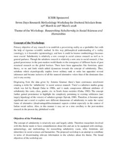
6 Cars with an automatic TRANSMISSION have no clutch that disconnects the TRANSMISSION from the engine. So, they use an amazing device called a torque converter. Torque converter:- What s Inside The Torque Converter? There are four components inside the very strong housing of the torque converter: Pump Turbine Stator TRANSMISSION fluid These are the parts in the figure turbine,stator,pump (left to right). The housing of the torque converter is bolted to the flywheel of the engine, so it turns at whatever speed the engine is running at. The pump inside a torque converter is a type of centrifugal pump. As it spins, fluid is flung to the outside. As fluid is flung to the outside, a vacuum is created that draws more fluid in at the center. The fluid then enters the blades of the turbine, which is connected to the TRANSMISSION .
7 The turbine causes the TRANSMISSION to spin, which basically moves your car. The blades of the turbine are curved. This means that the fluid, which enters the turbine from the outside, has to change direction before it exits the center of the turbine. It is this directional change that causes the turbine to spin. In order to change the direction of a moving object, you must apply a force to that object -- it doesn't matter if the object is a car or a drop of fluid. And whatever applies the force that causes the object to turn must also feel that force, but in the opposite direction. So as the turbine causes the fluid to change direction, the fluid causes the turbine to spin. The fluid exits the turbine at the center, moving in a different direction than when it fluid exits the turbine moving opposite the direction that the pump (and engine) are turning.
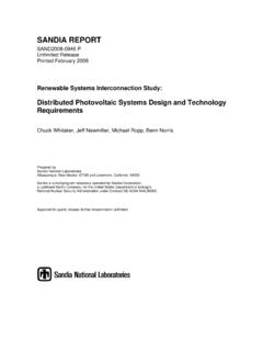
8 If the fluid were allowed to hit the pump, it would slow the engine down, wasting power. This is why a torque converter has a stator resides in the very center of the torque converter. Its job is to redirect the fluid returning from the turbine before it hits the pump again. This dramatically increases the efficiency of the torque converter. The stator has a very aggressive blade design that almost completely reverses the direction of the fluid. A one-way clutch (inside the stator) connects the stator to a fixed shaft in the TRANSMISSION (the direction that the clutch allows the stator to spin is noted in the figure above). Because of this arrangement, the stator cannot spin with the fluid -- it can spin only in the opposite direction, forcing the fluid to change direction as it hits the stator blades.
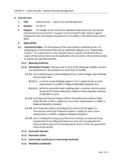
9 The figure (top to bottom) shows the pump,turbine and the stator, sending the fluid in their respective direction. Intersting facts about stator !!! Something a little bit tricky happens when the car gets moving. There is a point, around 40 mph (64 kph), at which both the pump and the turbine are spinning at almost the same speed (the pump always spins slightly faster). At this point, the fluid returns from the turbine, entering the pump already moving in the same direction as the pump, so the stator is not needed. Even though the turbine changes the direction of the fluid and flings it out the back, the fluid still ends up moving in the direction that the turbine is spinning because the turbine is spinning faster in one direction than the fluid is being pumped in the other direction.
10 If you were standing in the back of a pickup moving at 60 mph, and you threw a ball out the back of that pickup at 40 mph, the ball would still be going forward at 20 mph. This is similar to what happens in the turbine: The fluid is being flung out the back in one direction, but not as fast as it was going to start with in the other direction. Manual TRANSMISSION SYSTEM :- In this type of TRANSMISSION SYSTEM , the driver has to manually select and engage the gear ratios -: Clutch fully depressed The clutch is fully disengaged when the pedal is fully depressed. There will be no torque being transferred from the engine to the TRANSMISSION and wheels. Fully depressing the clutch allows the driver to change gears or stop the vehicle. Clutch slips The clutch slips is the point that vary between being fully depressed and released.