Transcription of Ionization Interference in Inductively Coupled Plasma ...
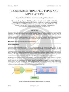
1 INDUSTRIAL MATERIALS. Ionization Interference in Inductively Coupled Plasma - Optical Emission Spectroscopy Yosuke MORISHIGE* and Atsushi KIMURA. Inductively Coupled Plasma -optical emission spectroscopy (ICP-OES) is widely used in various high-sensitive and high-precision elemental analysis such as environmental analysis and material analysis. Although the influence of coexisting elements on ICP-OES is known to be relatively small, in the axially viewed ICP-OES, the measurement error due to Ionization Interference could be observed depending on the combinations of coexisting elements and analyte elements. The result of the study on elemental combinations clearly shows that the occurrence of Ionization Interference can be presumed from the magnitude of Ionization potentials.
2 After examining the methods for adding low Ionization potential elements to both sample solution and standard solution, it was confirmed that Ionization Interference could be successfully suppressed by adding low Ionization potential elements, especially excessive amounts of cesium. 1. Introduction detector, and a data processing system, and is cus- tomized for various purposes. ICP-OES works by spray- Inductively Coupled Plasma -optical emission spec- ing the sample solution into a high-temperature Plasma troscopy (ICP-OES) is a quantitative method for deter- generated by subjecting argon gas to a high frequency mining trace elements in liquid samples. ICP-OES has field. The elements in the solution are determined qual- characteristics such as high sensitivity, high reliability, itatively and quantitatively from the wavelengths and wide dynamic range, and relatively less affected by coex- intensities of the emissions from excited atoms and ions.
3 Isting elements. It is used in a wide range of fields, Of the emissions spectra utilized for element determina- including purity analysis of environmental water and tion, the emission spectra from atoms are classified as composition analysis and contaminant analysis of plat- neutral lines, and the emission spectra from ions are ing solutions and materials such as metals, ceramics, classified as ionic lines. When ICP-OES is used for quan- and plastics (1). Recently ICP-OES is increasingly being titative analysis, a calibration solution adjusted to a applied for microanalysis of elements regulated by known concentration of the analyte element is generally RoHS, REACH and other standards. When utilizing prepared, and the concentration of analyte element is ICP-OES, the concentrations of coexisting elements in determined by comparing the intensity of emissions the sample solution and the calibration solution are from the sample solution and the calibration solution.
4 Usually adjusted to be the same in order to minimize the As shown in Fig. 1, two different photometry meth- influence of coexisting elements on measurement . ods are used in ICP-OES. Axial view is observation from However, this approach cannot be used when a sample the direction parallel to the Plasma , and radial view is consists of high-purity materials or contains unknown observation from the direction perpendicular to the elements. In some cases, whether or not the measure- ment was influenced by coexisting elements cannot be determined from measurement data. Therefore it is Detector important to improve the reliability of analysis by pre- liminarily determining the conditions of Interference by Ar Plasma source coexisting elements and how to avoid the occurrence of Interference .
5 In this study, the authors focused on ion- ization Interference due to coexisting elements, and Spectrometer examined its influence in various combinations of coex- Data processing system isting elements and analyte elements. The authors report also on a measure for suppressing Ionization Sample solution Interference and its success. Sample introduction section Ar Plasma Excitation coil Axial Ar gas view 2. ICP-OES Sample solution Torch Radial view Figure 1 shows the schematic of typical ICP-OES. equipment. The instrument is comprised of a sample introduction section, a Plasma source, a spectrometer, a Fig. 1. Schematic of ICP-OES. 106 Ionization Interference in Inductively Coupled Plasma -Optical Emission Spectroscopy Plasma .
6 Radial view is less affected by coexisting ele- enabling all wavelengths to be measured simultaneously. ments but has lower sensitivity, whereas axial view is It also permits switching between axial view and radial greatly affected from coexisting elements but provides view to be performed without reassembling the instru- greater detection sensitivity, more than 10 times that of ment. The ICP-OES measurement conditions are shown radial view for some elements. Recent ICP-OES instru- in Table 1. ments include models having both axial and radial view capabilities that allow the direction of observation to be selected to suit the sample and measurement range. Table 1. ICP-OES measurement conditions Traditional ICP-OES instruments generally used photo- Item Condition multipliers as detectors and utilized diffraction gratings RF power 1150W.
7 To scan the wavelengths. Recently, instruments using a semiconductor detector that can observe all wavelengths Flow rate of assist gas at the same time have become commercially available. Flow rate of nebulizer gas As a result of these developments, ICP-OES instruments Flow rate of coolant gas 12L/min. are becoming increasingly convenient to use. 3. Ionization Interference 5. Investigation of influence of Ionization Interference ICP-OES and other methods of spectrochemical analysis are typically subject to errors due to the four dif- 5-1 Experimantal method ferent types of Interference : 1) physical Interference Coexisting elements and analyte elements for the due to changes in viscosity, etc. of the solution, 2) chem- experiment were selected arbitrarily from elements with ical Interference due to the generation of compounds first Ionization potential up to about 10 eV.
8 The selected that have low atomization efficiency, 3) spectral interfer- elements are listed in Table 2. Neutral lines were select- ence due to the superposition, etc. of emission/absorp- ed as the measurement wavelengths, but ionic lines were tion lines, and 4) Ionization Interference due to changes measured for Ba and Y because these elements have no in Ionization equilibrium state. measurable neutral lines. For the sample solution, coex- Ionization Interference is a phenomenon which isting elements and analyte elements were added to shows a change in emission intensity, causing the ioniza- attain the concentrations shown in Table 2, then after tion equilibrium to shift, when coexisting elements adding 5 ml of 60% HNO3, the solution was diluted to include easily ionizable elements such as Na, K, Rb, and 100 ml with ultrapure water.
9 The calibration solutions Cs. Generally, this results in greater intensity of neutral were prepared with the element added in three levels, 0, lines and reduced intensity of ionic lines. It had been 1, and 3 g/ml for an analyte element concentration of reported that ICP-OES is significantly affected by physi- cal Interference and spectral Interference , but relatively less affected by the other two types of Interference (1). Table 2. Lists of coexisting elements and analyte elements However, Ionization Interference is known to affect ICP- Coexisting element Analyte element OES when the coexisting elements are easily ionizable elements, such as alkali metals. This is particularly a 1st Ionization 1st Ionization Concentration Concentration Wavelength Element potential Element potential large problem in axial view, since the emissions spectra (mol/l) ( g/ml) (nm).
10 (eV)(1) (eV)(1). are observed over the entire range of Plasma . It has Cs K 3 been confirmed that while detection sensitivity is K Na 3 enhanced, the influence of Ionization Interference also increases. There are some reports discussing how the Na Ba 1 direction of observation affect measurement result (2)-(5). Ba Li 1 Following the adoption by Sumitomo Electric Li Al 1 Industries, Ltd. of an ICP-OES unit capable of both axial In Y 1 view and radial view, the authors investigated the influ- ence of Ionization Interference and methods for sup- Al Mo 1 pressing such Interference . Ga Pb 3 Cr Mn 1 Ni Ni 1 4. Instrument and conditions for measurement Cu Cu 1 B Ge 1 The instrument used was an iCAP 6500 Duo ICP Zn B 1 spectrometer manufactured by Thermo Fisher Scientific P Cd 1 This instrument consists of a charge injection Zn 1 device (CID) detector and an echelle spectrometer, SEI TECHNICAL REVIEW NUMBER 66 APRIL 2008 107.