Transcription of IPC-TM-650 TEST METHODS MANUAL
1 1 ScopeThese METHODS determine the physical enduranceof representative coupons of printed boards to a series of hightemperature excursions from ambient. The temperatureexcursions cause thermo-mechanical fatigue of the electricalinterconnect test coupon is resistance heated by passing DC currentthrough the coupon to bring the temperature of the copper toa designated temperature. Switching the current on and offcreates thermal cycles between room temperature and thedesignated temperature within the sample. The laminate andsurrounding materials are heated to different extents depend-ing on the thermal conductivity of the materials. The thermalcycling can accelerate latent interconnect anomalies to number of cycles achieved permits a quantitative assess-ment of the Method A DescriptionMethod A uses a coupon withtwo or more independent electrical nets. The designation forthese nets is either a power net (P) or a sense net (S). Eachelectrical net consists of plated barrels and conductors (inter-nal and external).
2 DC current is passed through one electricalnet to heat the coupon to a designated temperature. Whenthe electrical net is at the designated temperature, the DCcurrent is turned off and cooling fans are turned on to cool thecoupons to ambient temperature. One heating and coolingsequence represents a thermal cycle. Thermal cycling is con-tinued to either a set number of cycles or a failure. Tempera-ture coefficient of resistance (TCR) is estimated by failure is based on a percentage change in the bulk resis-tance of the coupon at the designated test temperature. Thepercentage change is measured independently for each elec-trical net being tested. When the percentage change isexceeded, the test is stopped for the Method B DescriptionMethod B uses a coupon withone electrical net. The net consists of via structures con-nected by external and/or internal circuit lines in a daisy current is passed through the electrical net to heat thecoupon to a designated temperature.
3 When the electrical netis at the designated temperature, the DC current is turned offand a cooling fan is turned on to cool the coupons to ambienttemperature. One heating and cooling sequence represents athermal cycle. Thermal cycling is continued to either a setnumber of cycles or a failure. Temperature coefficient of resis-tance (TCR) is failure is based on a percentage change in the bulk resis-tance of the coupon at the designated test temperature. Thepercentage change is measured independently for each elec-trical net being tested. When the percentage change isexceeded, the test is stopped for the Applicable IPC1 IPC-MDP-650 Method Development PacketIPC-TM-650 Test METHODS of Printed Board Substrates AfterExposure to Assembly, Rework, and/or ReliabilityTests. (At the time of publication of this test method, is in development.) Stress, Convection Reflow AssemblySimulation3 Test SpecimensA typical daisy chain test coupon foreach method is shown in Figure 3-1 and Figure Current and revised IPC Test METHODS are available on the IPC Web site ( )3000 Lakeside Drive, Suite 309 SBannockburn, IL 60015-1249 IPC-TM-650 TEST METHODS Current Induced Thermal Cycling TestDate5/14 RevisionAOriginating Task GroupPTV Reliability Test METHODS (6-10c)Material in this Test METHODS MANUAL was voluntarily established by Technical Committees of IPC.
4 This material is advisory onlyand its use or adaptation is entirely voluntary. IPC disclaims all liability of any kind as to the use, application, or adaptation of thismaterial. Users are also wholly responsible for protecting themselves against all claims or liabilities for patent referenced is for the convenience of the user and does not imply endorsement by 3-1 Method A Test CouponIPC-2626-3-2 Figure 3-2 Method B Test Current Induced Thermal Cycling TestDate5 Coupon Design RulesCertain designs rules must beapplied to achieve thermal uniformity. Electronic design filesfor coupon construction are available from the equipmentsupplier or printed board supplier. The resistance values (volt-age drops) for each coupon are monitored independently foreach electrical net in test, using a four wire test coupon(s) is incorporated on the panel to monitor orqualify design, materials, or processes of product and/or reli-ability Apparatus or MaterialAt the time of publication of thistest method, and list the only known equipmentmanufacturers of this test equipment.
5 Equivalent test systemsmay be used that operate on principles similar to those iden-tified in Method A or B. IPC encourages their submissionalong with relevant validation test data. This test method willbe revised as necessary to include these test systems as thisinformation becomes of this test method was performed with the equip-ment listed in and Test conditions for the validationare provided in If alternate test equipment is used, valida-tion in accordance with IPC-MDP-650 and is Method equipment is available from:PWB Interconnect Solutions Inc. (Canada)URL: Type: (2) four-pin, mm [ in] male connector(ITW Pancon MFSS100-4-D or equivalent). , Sn63Pb37, or lead free Method equipment is available from:i3 Electronics (USA)(formerly Endicott Interconnect Technologies)URL: Type: CITC, multimeter, capable of measuring imaging equipment optional5 Sample top measure the resistance of each net of thecoupon with a 4-wire multimeter.
6 A net with an open cannotbe tested. A net with a short must be reworked to test Coupon SelectionSelect coupons for evaluationbased upon the test required as described in Random SamplingA sample chosen withoutregard to any characteristic of the individual coupons within apopulation, within one or more Selective SamplingA sample chosen based onthe resistance measurements of the sense and power may include high, midrange and low resistance Comparative SamplingA sample chosen basedon the resistance measurements of the sense and powernets. Testing should include similar resistance measurementsfor the populations being Method A Single Sense TestingSolder two four-pin male con-nectors in the mm [ in] holes at the left and rightedges of the coupon (see Figure 3-1). A solder fillet must beapparent on both sides of the Dual Sense Testing (Optional)When Dual SenseTesting is required, solder three four-pin male connectors inthe mm [ in] holes at the edges of the coupon (seeFigure 5-1).
7 A solder fillet must be apparent on both sides ofthe :Dual Sense coupons may be tested using the SingleSense Testing Current Induced Thermal Cycling TestDate5 the coupons at each test head by attachingmale to female Baseline Performance (Optional)Establish a per-formance baseline by completing two Method A cycles andthen stop the test at the end of the cooling Capacitance Test (Optional)If required, the capaci-tance testshallbe performed per IPC-TM-650 , Assembly Precondition (Optional)Assembly pre-conditioning is recommended to simulate the assembly envi-ronment to which the printed boards are exposed (see ). otherwise specified by the user, test all viatypes and materials per the default test condition in accor-dance with Table 5-1. For testing of samples containingmicrovia structures, use the microvia test condition. For test-ing of samples containing polyimide materials, use the polyim-ide test Pre-Cycling Test SequenceThe following para-graphs detail the sequence for a single coupon, however thissequence is done at all test heads simultaneously.
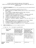
8 The ambi-ent resistance, resistance at test temperature, rejection resis-tance, and current are calculated for each coupon and dis-played on the PC 5-1 Examples of Three Dual Sense IST Test Coupons(Top-Down View as shown at left and Isometric View as shown at right)Table 5-1 Method A Typical Test ConditionsTestConditionNumberof SamplesTestTemperaturesFailureThreshold( ResistanceChange)1 Numberof CyclesDataCollectionFrequency(Cycles)Pre cycleTimeWindow(seconds)CompensationDefa ult6150 C10%250253 CalculatedPolyimide6 AABUS10%250253 CalculatedMicrovias26190 C10%250253 NonePolyimideMicrovias26 AABUS10%250255 NoneSurvivabilityTesting6230 C10%1015 None6245 C10%1015 None6260 C10%1015 NoneNote Dual Sense Testing, both the Cycle Using and the Cycle Failing On fields on the Method A test equipmentshallbe set to both sense circuits. Note on the microvia or heating trace Current Induced Thermal Cycling TestDate5 Ambient ResistanceThe auto ranging multimetermeasures the ambient resistance (voltage drop) of the net thatheats the coupon with DC Resistance at Test TemperatureThe systemsoftware calculates and displays the resistance at the testtemperature.
9 The available stress testing range is from 50 -270 C [122 - 518 F]. The equation used to calculate the tar-get resistance is as follows:Target Resistance = Rrm x (1 + T [Th - Trm])where: T = Estimated thermal coefficient of resistance for the inter-connectRrm = Resistance of coupon at ambient temperatureTh = Test temperatureTrm = Ambient Temperature (approximately 25 C [77 F]) Failure ThresholdThe system software calculatesand displays the resistance change. This is adjustable from a1% to a 100% increase. The typical failure threshold value is a10% change in resistance. The equation to calculate the fail-ure threshold is as follows:Failure Threshold = (RT1 x Rr) + RT1where:Failure Threshold is in resistanceRT1 = Resistance of coupon at test temperature for Cycle 1Rr = Resistance change (typically 10%) CurrentThe system selects an initial current basedon the ambient resistance of the coupon and the currenttable. The current tables are derived from software libraries onthe Method A test equipment.
10 During the pre-cyclingsequence, the initial current is adjusted for each coupon toassure the test temperature resistance is achieved in threeminutes precycle time window (see ).NOTE:Additional equations/algorithms used by Method Athat establish the initial current selection for pre-cycling, rela-tive to the relationship of coupon interconnect resistance T,coupon construction and stress test temperature to beachieved are considered proprietary at this Pre-CyclingPre-cycling is initiated by the applica-tion of the selected current to the coupon; the computermonitors the coupon s performance throughout a 30 secondand 60 second cycle. The resistance level is monitored andthe current is adjusted based on the resistance short duration tests adjust the current to prevent thecoupon heating rate being too fast on the first pre-cycle. Thecomputer monitors and records the coupon s performance onthe first pre-cycle. If at the end of the first pre-cycle, the cou-pon achieves the specified resistance level in three minutes precycle time window, it will be accepted for subsequentstress testing.