Transcription of IRD Balancing B140-200K
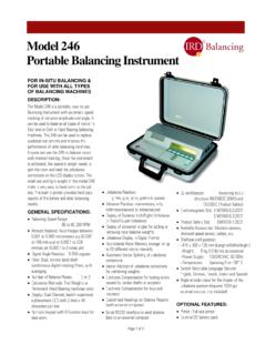
1 Page 1 of 12 B140- 200k Series 90000 kg (200000 lb) Performance Specifications for Model B140 Balancing Machine 90000 kg (200000 Pounds) Capacity End Drive/Machining Type 1. GENERAL DESCRIPTION Balancing Machine The Model B140 is a dynamic, horizontal axis, soft bearing Balancing machine. It uses moving coil transducers to measure the motion of an unbalanced rotor on freely moving suspensions. The machine must be firmly mounted to a standard reinforced concrete floor, but does not require any special foundation. In order to provide an easy to use transportable mounting method, track clamps are provided to lock the pedestals and console to an existing railroad track or an optional prefabricated railroad track bed assembly.
2 The Model B140 has an End Drive console with a variable speed motor and multi-speed gearbox for efficient transfer of torque to the rotor. The End Drive system uses a cardan shaft (supplied) to spin the rotor. Adapters to attach the cardan shaft to the rotor are the customers responsibility. The use of a cardan shaft may require the use of electronic tooling compensation (a feature in the Model 295 instrument) to eliminate errors due to fit-up and/or unbalance in the adapter tooling. The machine and instrument are easy to set up and use. The standard calibration method uses trial weights to calibrate the rotor to the Balancing instrument for the most accurate possible unbalance readout.
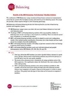
3 Instrumentation The standard Balancing instrument is the Model 295 which has large digital display meters and shaft synchronous digital filters. Dynamic (Left/Right), Static and Couple unbalance can be displayed, individual workpiece setups can be stored and the balance results can be printed on an external printer. The instrument also displays the angle position of the rotor to aid in placing the correction weights on the rotor. Detailed specifications on the 295 instrument are separate from these performance specifications. Page 2 of 12 B140- 200k Series 90000 kg (200000 lb) Figure 1 - B140 Balancing Machine Page 3 of 12 B140- 200k Series 90000 kg (200000 lb) 2.
4 SPECIFICATIONS Rotor Mass and Unbalance Limitations Maximum weight capacity Standard Roller Bearings (270 mm) 90000 kg (200000 pounds) Maximum weight per support Standard Roller Bearings (270 mm) 56700 kg (125000 pounds) Capacity Note: Total rotor weight cannot exceed the maximum capacity of paragraph Minimum weight Standard Roller Bearings (270 mm) 450 kg (1000 pounds) Minimum Achievable Residual Unbalance (Umar) per plane under g mm/kg (.004 g in/lb) ideal rotor conditions but not less than 180 g mm (7 g in) Unbalance Reduction Ratio 95% Rotor Dimensions Maximum rotor diameter 3900 mm (154 inches) (with Standard Rollers) Maximum distance between support Limited Only by Installation bearing centerlines Space Available Minimum distance between support 915 mm (36 inches) bearing centerlines Journal diameters accommodated on roller bearings (Sets 2 4 optional) Set 1 (270 mm diameter) 300 to 800 mm (12 to 32 inches) Set 2 (260 mm diameter) 100 to 500 mm (4 to 20 inches)
5 (weight capacity range 230 kg to 36300 kg per pair) Set 3 (200 mm diameter) 60 to 710 mm ( to 28 inches) (weight capacity range 230 kg to 22700 kg per pair) Set 4 (160 mm diameter) 180 to 300 mm (7 to 12 inches) (weight capacity range 230 kg to 22700 kg per pair) Rotor Centerline from Floor On 60 mm Journal diameter 1532 mm ( inches) On 800 mm Journal diameter 1955 mm (77 inches) Maximum Difference in Rotor Journal 229 mm (9 inches) Diameters with Equal Diameter Rollers Height Adjustment Travel (total) 114 mm ( inches) Page 4 of 12 B140- 200k Series 90000 kg (200000 lb) 2. SPECIFICATIONS (continued) Drive System Type of drive system End Drive, DC Motor with multi-speed gearbox and adjustable length Cardan Shaft Cardan Shaft, Heavy Duty, Precision, Adjustable Length Type Universal Joint Length 915 to 1030 mm (36 to inches) Weight 66 kg (145 pounds) Maximum Torque 8800 N m (6500 lb ft) Angle from Horizontal Maximum 12 For stated Umar 3 Maximum Unbalance Error Non-Systematic 8625 g mm (340 g in) (with axial adjustment see note 1) Systematic 1440 g mm (56 g in) (see notes)
6 Note errors are errors whose maximum value is known, but cannot be compensated by index Balancing . The maximum non-systematic unbalance error includes driveshaft unbalance, eccentricity in mounting the driveshaft to the rotor and misalignment or eccentricity in the axial adjustment mechanism. The listed error is for a mounting eccentricity of mm ( inches) between the geometric centerline of the rotor (determined by the two journal support surfaces) and the geometric centerline of the driveshaft (determined by the machined male rabbet diameter). Note 2. Systematic errors are repeatable errors that can be compensated by index Balancing .
7 Note 3. Additional systematic unbalance measurement errors (due to unbalance and eccentricity) occur when adapters are used between the rotor and the driveshaft. These should be estimated and added to the driveshaft errors to determine the total error due to the attachment tooling. Motor DC Variable Speed, Drip Proof Frame and Cooling Blower, Mounted inside control console Supply voltage (specify frequency on order) 460 Mains Power 460 VAC, 50 or 60 Hz 3 Phase, 116 A Rated Output Power 56 kW (75 HP) Recommended Drive Isolation Transformer Input Power rating 93 KVA Page 5 of 12 B140- 200k Series 90000 kg (200000 lb) 2.
8 SPECIFICATIONS (continued) Output Torque, Maximum At motor 464 N m (343 pound feet) At Cardan Shaft (Gear #9) 1045 N m (771 pound feet) At Cardan Shaft (Gear #5) 3553 N m (2620 pound feet) At Cardan Shaft (Gear #1) 13218 N m (9749 pound feet) Acceleration Torque Same as output torque, Section Braking Torque Same as output torque, Section Motor speed, Maximum At motor 1150 RPM At Cardan Shaft (Gear #9) 511 RPM At Cardan Shaft (Gear #5) 150 RPM At Cardan Shaft (Gear #1) 40 RPM (slow roll, machining only) Type of brake Regenerative with supplementary dual air actuated disk brake for rotor holding Motor and Controller To NEMA and AMT standards Controller Speed range 20:1 Balancing speed 70 to 511 RPM Slow Roll/Machining Speed to 61 Gearbox Multi-speed, Heavy Duty Gearbox with 11 speed ranges.
9 Gearbox is located inside control console and is shifted only under no load conditions. GEAR MIN. RPM MAX. RPM Low Rev 39 Hi Rev 131 1 40 2 61 3 82 4 112 5 150 6 208 7 279 8 381 9 511 Air Supply Requirement 480 to 690 kPa at m /h (70 to 100 psi at cfm) Page 6 of 12 B140- 200k Series 90000 kg (200000 lb) 3. MACHINE COMPONENTS Machine Bed No Machine Bed is required. The pedestals and console attach directly to any existing railroad spur, either flush with the floor or on top of the floor. If railroad track is not available, the pedestals and console can be directly lagged to the concrete floor.
10 An optional Railroad Track Bed Assembly is available that provides the benefit of a railroad spur but with the advantage that it can transported with the machine and be placed on any concrete floor. Work Supports Two super critical (above resonance) pedestals with high output moving coil vibration transducers support the rotor to be balanced. The transducer calibration is traceable to National Institute of Standards & Technology (USA). (Transducers are furnished with Balancing Instrument). Both work supports contain a manually adjustable height adjustment mechanism for leveling rotors with unequal diameter journals.