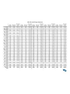
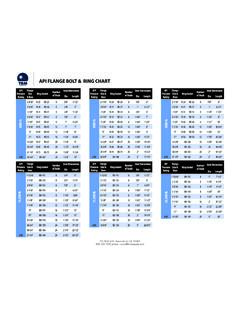
Transcription of ISO 6162 — Four-Bolt Flange Connection (Includes SAE J518)
1 U28 Parker Hannifin CorporationTube Fittings DivisionColumbus, Catalog General TechnicalDimensions and pressures for reference only, subject to 6162 Four-Bolt Flange Connection (Includes SAE J518) NOTE: For assembly procedure and torques, see page U19 Port Detail ISO 61621) 1 MPa = 10 bar = 145 ) Not for new ) 90 durometer nitrile is standard for hydraulic ) 16 mm is also acceptable. Nominal to MPa Series1) Flange (SAE Code 61) O-Rings3) Size Clamping Screws Flange Half and Bolt Pattern D3 Screw Holes Parker Type I Type II2) (SAE J518) C J W Y L5 L6 ISO 3601-1 O-Ring (in) (mm) Thread t1 Min. depth Thread (UNC) t1 Min. depth max. min. Ref.
2 ID x Section Size 1/2 13 M8 x 5/16 - 18 24 46 13 19 19 x 2-210 3/4 19 M10 x 3/8 - 16 22 52 14 22 25 x 2-214 1 25 M10 x 3/8 - 16 22 59 16 22 x 2-219 1 1/4 32 M10 x 7/16 - 14 28 73 144) 24 x 2-222 1 1/2 38 M12 x 1/2 - 13 27 83 16 25 x 2-225 2 51 M12 x 1/2 - 13 27 97 16 26 56 x 2-228 2 1/2 64 M12 x 1/2 - 13 30 109 19 38 69 x 2-232 3 76 M16 x 2 5/8 - 11 30 131 22 41 85 x 2-237 3 1/2 89 M16 x 2 5/8 - 11 33 140 22 28 x 2-241 4 102 M16 x 2 5/8 - 11 30 152 25 35 112 x 2-245 5 127 M16 x 2 5/8 - 11 33 181 28 41 136 x 2-253 Nominal 40 MPa Series1) Flange (SAE Code 62) O-Rings3)
3 Size Clamping Screws Flange Half and Bolt Pattern D3 Screw Holes Parker Type I Type II2) (SAE J518) C J W Y L5 L6 ISO 3601-1 O-Ring (in) (mm) Thread t1 Min. depth Thread (UNC) t1 Min. depth max. min. Ref. ID x Section Size 1/2 13 M8 x 5/16 - 18 21 48 16 22 19 x 2-210 3/4 19 M10 x 3/8 - 16 24 60 19 28 25 x 2-214 1 25 M12 x 7/16 - 14 27 70 24 33 x 2-219 1 1/4 32 M12 x 1/2 - 13 25 78 27 38 x 2-222 1 1/2 38 M16 x 2 5/8 - 11 35 95 30 43 x 2-225 2 51 M20 x 3/4 - 10 38 114 37 52 56 x 2-228 Return To Index