Transcription of ISO 9001:2008 CERTIFIED Jr. & Sr. Bolted Gauge …
1 Jr. & Sr. Bolted Gauge InstallationISO 9001:2008 CERTIFIEDMS-501/502 Mounting StandardThe Measure of ExcellenceSee reverse side for dimensional data, materials of construction, performance, and advice on how to COMPLETELY BEFORE AT TEMPT ING INSTALLATIONWARNING:Improper installation or misuse of this prod uct maycause serious injury or property dam INSTRUCTIONS ARE PRE PARED TO ASSISTTRADES MEN AND OTH ERS QUALIFIED TO SERVICELIQUID STORAGE TANK EQUIPMENT. CONSUMERS ARENOT QUAL I FIED TO PERFORM THE IN STAL LA TION DE -SCRIBED BELOW.
2 IF YOU HAVE ANY QUESTIONS CON -CERN ING IN STAL LA TION OR OPERATION OF THEGAUGE OR GASKET, CONTACT ROCH ES TER GAUGES,INC. OR ONE OF OUR AUTHORIZED DIS TRIB U TORSFOR ASSISTANCE. CHECK SIDE OF Gauge HEAD FORMODEL NUMBER AND ASK FOR Gauge INSTALLATIONIN STRUC TIONS FOR YOUR MOD THE Gauge RIGHT FORYOUR AP PLI CA TION?Gauges should only be installed in applications rec om mend ed by themanufacturer. Verify that the Gauge is the proper Gauge for your appli-cation prior to at tempt ing float may or may not have a counterbalance de pend ing on theintended application.
3 Applications for light specific gravity liquids orlarge tanks nor mal ly require counterbalancing of the Gauge , mounting gasket and mounting adapter (if ap pli ca ble)must be constructed of materials com pat i ble with the liquid to bemeasured and the service en vi ron ment. The float, mounting boltsand head must be adequately rated for your specific pressure andtem per a ture THE Gauge THE PROPER SIZE?As a general rule, the float pivot point should be on the horizontalcenterline of the tank when installed. The float length dimension(measured from the float pivot point to the end of the float) shouldbe pro por tion al to the inside tank height and is usually slightly lessthan 1 2of the vertical inside height of the can be constructed for side, top or angle mount ing but mustbe installed in the po si tion for which they are constructed.
4 Hold thegauge by the support (see Figure A) in the intended mounting atti-tude and operate the float to see if it is correct for your application(see Figure B).CAUTION:Improper Gauge or dial selection or application mayresult in inaccurate read ings. Re lease of tank contents as well asdamage to equip ment and safety hazard may result if tank is over -filled. Fuel ex haus tion may occur if tank contents are less than indi-cated. LP Gas & NH3gauge dials re quire an appropriate tempera-ture :Determine and install the ap pro pri ate Gauge & gasketbased on system re quire ments.
5 The gasket type supplied may notbe suitable for all applications and for those ap pli ca tions other gas -ket ma te ri als may be available. The information con tained herein isintended for guide line use only and the suit abil i ty of any part for aparticular application must be determined by the user prior to instal-lation. Improper gasket se lec tion or ap pli ca tion may result in sealfailure, subsequent release of tank con tents and serious injury andor property :This Gauge is not a substitute for a fixed liquid levelgauge or weight mea sure ment device, which may be required forfilling.
6 This document is not instructions for tank REMOVAL WARNING:Should it ap pear necessary, toremove the Gauge from the tank, do not attempt removal unlessunder com pe tent su per vi sion with all due pre cau tions tak en againstthe hazards of re leased liquid or high pres sure and/or flammable :Even if a Gauge registers empty, tank may containhigh pressure and flammable gas. A hazard of fire or explosion mayexist if proper methods are not used when re mov ing or installing thegauge or gasket. Replace gasket if Gauge is removed.
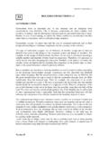
7 Do not reusegasket. FIGURE AFIGURE BFloat PivotFloat HeadCounter Balance (if required) H S F A Ver ti cal sup port,top mountInclined support,angle mount H1 S F A H F S Hor i zon tal sup port,Side or end mountSupportMS-501/502 Mounting StandardThe Measure of Excellence11616 Harry Hines Blvd. Box 29242 Dallas, TX 75229 (972) 241-2161 FAX(972) 620-3374 & Sr. Bolted Gauge InstallationNOTES:(1) Drill Letter I(.272 .279) DIA X .75 Cyl..3125 24 UNF 2B X .50 Full Thread Depth. TYP. 4 Places.(2) Drill MM (.216 .221) DIA X.
8 75 Cyl..250 28 UNF -2B X .50 Full Thread Depth TYP. 4 Places.(3) Tapped Holes To Be To Face Within 1 2 (4) Gasket Recess To Be With Bore Within .030 (5) Tapped Holes To Be With Gasket Recess Within .025 (6) Some SR. Industrial Gauges Are Furnished With .250 28 UNF 2A Mounting Bolts, For These Gauges Drill & Tap for .250 28 UNF And Not For .3125 24 UNF.(7) For SR. Industrial Gauges Using 0015 00079 Or Similar Flat Gasket, Delete .062 x Gasket :Do not over torque. Do not re-torque later unless leaking. Over tightening may cause damage to head and SIZE DRY TORQUE GASKET TYPE1 4-28 35 In.
9 Lb. [4 Nm] BUNA, NEOPRENE, VITON, TEFLON5 16-24 100 In. Lb. [11 Nm] BUNA, NEOPRENE, VITON, TEFLON5 16-24 125 In. Lb. [14 Nm] NEOPRENE, NARROW, YELLOW STRIPE (Refrigerant Applications)5 16-24 125 In. Lb. [14 Nm] BUNA N, NARROW, WHITE STRIPE (Refrigerant Applications)5 16-24 240 In. Lb. [27 Nm] SPIRAL WOUND GASKET (used with stainless steel head and special mounting screws)* Materials and specifications are subject to change with out notice. Pressure ratings sub ject to change due to tem per a ture and other en vi ron men tal 502 SR.
10 GAUGES [See MS-512 for Metric]SEE NOTE 1, 6 & 7.+..008 .005 NOTE 2 DRAW ING NUMBERMS-501 & MS-502 installation * are normally fastened to tank using a mountingadapter which has previously been welded or otherwiseinstalled into the tank or it s fittings. Check adapter for correctdimensions and finish, see dimensions below. Check colorstripe on of gasket for ma te ri STRIPE= Senior part # 0015-00836 orJunior part # 0015-00855 recommended for anhydrous am mo niaand specific refrigerant :Adjustable gauges are NOT intended forammonia service.