Transcription of ISO3086T Isolated 5-V RS-485 Transceiver With …
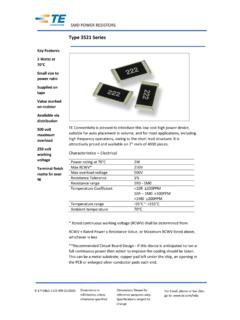
1 C212345678D1D2 VCC1 GND1 RREDEDVCC2 ABGND2 ZYC31614131211159, 10 OUTNCC6 INENGND51 LDO132C5C4D1D287654321C1X-FMRISO3086 TIsolated Supply toother ComponentsRS-485 BusInterfaceControlCircuitryProductFolde rSample &BuyTechnicalDocumentsTools &SoftwareSupport &CommunityReferenceDesignISO3086 TSLLSE27D JANUARY2011 REVISEDOCTOBER2015 ISO3086 TIsolated5-V RS-485 TransceiverWith IntegratedTransformerDriver1 Features3 DescriptionTheISO3086 Tis an isolateddifferentialline1 Meetsor ExceedsTIA/EIA-485-Atransceiverwithinteg ratedoscillatoroutputsthat SignalingRateup to 20 Mbpsprovidetheprimaryvoltageforanisolati on 1/8 Unit Load Up to 256 Nodeson a a full-duplexdifferentialline transceiverfor RS-485and RS-422applications ThermalShutdownProtectionthat can easilybe configuredfor
2 Half-duplexoperation TypicalEfficiency> 60%(ILOAD= 100 mA) - seeby connectingpin 11 to pin 14, and pin 12 to pin idealfor longtransmissionlines Low Bus Capacitance7 pF (Typ)sincethe groundloopis brokento allowfor a much 50-kV/ s symmetrical Fail-safeReceiverfor Bus Open,Short,Idleisolationbarrierof the deviceis testedto provide4242 VPKof isolationfor 1 minuteper VDEbetween LogicInputsare 5-V Tolerantthe bus-linetransceiverand the logic-levelinterface. Bus-PinESDP rotectionAny cabledI/O can be subjectedto electricalnoise 11-kVHBMB etweenBus-Pinsand 6-kVHBMB etweenBus-Pinsand GND1transientscancausedamageto the Transceiver Safetyand RegulatoryApprovalsand/ornear-bysensitiv ecircuitryif 4242 VPKB asicInsulationper DIN V VDEV devicescansignificantlyincreaseprotectio nand0884-10and DIN EN 61010-1reducethe riskof damageto expensivecontrol 2500 VRMSI solationfor 1 minuteper UL 1577circuits.
3 CSAC omponentAcceptanceNotice5A, IECTheISO3086 Tis specifiedfor use from 40 C to60950-1and IEC 61010-1 Standards85 ApplicationsDeviceInformation(1) IsolatedRS-485/RS-422 InterfacesPARTNUMBERPACKAGEBODYSIZE(NOM) FactoryAutomationISO3086 TSOIC(16) Motor/MotionControl(1) For all availablepackages,see the orderableaddendumatthe end of the datasheet. HVACand BuildingAutomationNetworks NetworkedSecurityStationsTypicalApplicat ionCircuit1An IMPORTANTNOTICEat the end of this datasheetaddressesavailability,warranty, changes,use in safety-criticalapplications,intellectual propertymattersand JANUARY2011 Contents1 Pin Configurationand Applicationand Deviceand Mechanical,Packaging,and Orderable7 RevisionHistoryNOTE:Pagenumbersfor previousrevisionsmay differfrompagenumbersin the (July2011)to RevisionDPage AddedFeatureItem"Meetsor ExceedsTIA/EIA-485".
4 1 VDEstandardchangedto DIN V VDEV 0884-10(VDEV 0884-10) AddedPin Configurationand Functionssection,ESDR atingstable,FeatureDescriptionsection,De viceFunctionalModes,Applicationand Implementationsection,PowerSupplyRecomme ndationssection,Layoutsection,Deviceand DocumentationSupportsection,andMechanica l,Packaging,and (July2011)to RevisionCPage AddedNote1 to the Changedthe TRANSFORMERDRIVERCHARACTERISTICS table- fStTestConditionsFrom:.VCC1= 9V To: VCC1= and Changedthe TYPvalueFrom:230 To: 350 (March2011)to RevisionBPage Deletedthe MIN and MAXvaluesfromrows,tr_d, tf_D, and tBBMof the (January2011)to RevisionAPage Changedthe Featuresand Changedthe datasheetFrom:PreviewTo: AddedFigure34 2011 2015, JANUARY2011 REVISEDOCTOBER20155 Pin Configurationand FunctionsDW Package16-PinSOICTop ViewPin , OpenDrainOutputD22 OTransformerDriverTerminal2, OpenDrainOutputD8 IDriverInputDE7 IDriverEnableInputGND13 Logic-sideGroundGND29, 15 are No pin is not connectedto any pin has Logic-sidePowerSupplyVCC216 Bus-sidePowerSupplyY11 ONon-invertingDriverOutputZ12 OInvertingDriverOutput6 (1)MINMAXUNITVCC1, VCC2 Inputsupplyvoltage(2) ,VB,VY,VZVoltageat any bus I/O terminal(A, B, Y, Z) 914 VVD1,VD2 Voltageat D1, D214VV(TRANS)Voltageinput,transientpulse through100 , see Figure27 (A, B,Y, Z)
5 5050 VVIV oltageinputat D, DE or RE terminal 1010mAID1, ID2 TransformerDriverOutputCurrent450mATJM aximumjunctiontemperature170 CTSTGS toragetemperature 65150 C(1)StressesbeyondthoselistedunderAbsolu teMaximumRatingsmay causepermanentdamageto the stressratingsonly and functionaloperationof the deviceat theseor any otherconditionsbeyondthoseindicatedunder RecommendedOperatingConditionsis not absolute-maximum-ratedconditionsfor extendedperiodsmay affectdevicereliability.(2)All voltagevaluesexceptdifferentialI/O bus voltagesare with respectto networkgroundterminaland are 2011 2015,TexasInstrumentsIncorporatedSubmitD ocumentationFeedback3 ProductFolderLinks:ISO3086 TISO3086 TSLLSE27D JANUARY2011 pins and GND1 6000 Humanbodymodel(HBM),per ANSI/ESDA/JEDECJS-Bus pins and GND2 11000001(1)ElectrostaticV(ESD)All pins 4000 VdischargeCharged-devicemodel(CDM),per JEDEC specificationJESD22-C101(2) 1500 Machinemodel(MM), 200(1)JEDEC documentJEP155statesthat 500-VHBM allowssafe manufacturingwith a standardESDcontrolprocess.
6 (2)JEDEC documentJEP157statesthat 250-VCDM allowssafe manufacturingwith a V V VICV oltageat any bus terminal(separatelyor common-mode) 712 VRE2 VCC1 VIHHigh-levelinputvoltageVD, , VCC1A with respectto B 1212 VIDD ifferentialinputvoltageVDynamicSee Figure16 RLDifferentialload resistance5460 Driver 6060 IOOutputCurrentmAReceiver 88 TAAmbienttemperature 4085 CTJO peratingjunctiontemperature 40150 C1 / (1)DW (SOIC)UNIT16 PINSR C/WR JC(top)Junction-to-case(top) C/WR C/W C/W C/W(1)For moreinformationabouttraditionaland new thermalmetrics,see theSemiconductorand IC PackageThermalMetricsapplicationreport, (unlessotherwisenoted)PARAMETERTESTCONDI TIONSVALUEUNITVCC1= VCC2= ,TJ= 150 C, RL= 54 ,CL= 50pF(Driver),CL= 15pF(Receiver),PDMaximumdevicepowerdissi pation490mWInputa 10 MHz50%duty cyclesquarewaveto Driverand Receiver4 SubmitDocumentationFeedbackCopyright 2011 2015, JANUARY2011.
7 Driveroverrecommendedoperatingconditions (unlessotherwisenoted)PARAMETERTESTCONDI TIONSMINTYPMAXUNITIO= 0 mA, no 54 ( RS-485 ),See |VOD|DifferentialoutputvoltagemagnitudeV RL= 100 (RS-422),See 7 V to +12 V, magnitudeof the differential |VOD|See Figure17 and Figure18 (SS) steady-statecommon-mode VOC(SS) (pp)Peak-to-peakcommon-modeoutputvoltage See , DE, VIat 0 V or VCC1 1010 AVYor VZ= 12 V,1 VCC2= 0 V or 5 V, DE = 0 VHigh-impedancestateoutputcurrent,Y or ZOtherbus pinIOZ Apinat 0 VVYor VZ= 7 V, 1 VCC2= 0 V or 5 V, DE = 0 VOtherbus pinIOS(1)Short-circuitoutputcurrent 7 V VYor VZ 12 V 250250mAat 0 V(1)This devicehas thermalshutdownand outputcurrentlimitingfeaturesto protectin short-circuitfault :Receiveroverrecommendedoperatingconditi ons(unlessotherwisenoted)PARAMETERTESTCO NDITIONSMINTYPMAXUNITVIT(+)Positive-goin ginputthresholdvoltageIO= 8 mA 85 10mVVIT( )Negative-goinginputthresholdvoltageIO= 8 mA 200 115mVVhysHysteresisvoltage(VIT+ VIT )30mVVCC1= VVCC1 200 mV, IO= 8 mA,VOHHigh-leveloutputvoltageVSee Figure23 VCC1= 5 200 mV, IO= 8 mA,VOLLow-leveloutputvoltageVSee Figure23 VCC1= 5 (Z)High-impedancestateoutputcurrentVO= 0 or VCC1, RE = VCC1 11 AVAor VB= 12 V40100 VAor VB= 12 V, VCC2= 060130 OtherinputIA, IBBus inputcurrent Aat 0 VVAor VB= 7 V 100 40 VAor VB= 7 V, VCC2= 0 100 30 IIHHigh-levelinputcurrent,REVIH= 2.
8 V 1010 AIILLow-levelinputcurrent,REVIL= V 1010 RIDD ifferentialinputresistanceA, B96k CIDD ifferentialinputcapacitanceVI= sin (4E6 t) + (unlessotherwisenoted)PARAMETERTESTCONDI TIONSMINTYPMAXUNITVCC1= 5 V 10%,D1 and D2 connectedto350450610transformerfOSCO scillatorfrequencykHzVCC1= V 10%,D1 and D2 connectedto300400550transformerRONS witchon resistanceD1 and D2 connectedto 50 Copyright 2011 2015,TexasInstrumentsIncorporatedSubmitD ocumentationFeedback5 ProductFolderLinks:ISO3086 TISO3086 TSLLSE27D JANUARY2011 (continued)overrecommendedoperatingcondi tions(unlessotherwisenoted)PARAMETERTEST CONDITIONSMINTYPMAXUNITVCC1= 5 V 10%,see Figure29,(1)80tr_DD1, D2 outputrise timensVCC1= V 10%,see Figure29,(1)70 VCC1= 5 V 10%,see Figure29,(1)55tf_DD1, D2 outputfall timensVCC1= V 10%,see Figure29,(1)80fStStartupfrequencyVCC1= V, D1 and D2 connectedto transformer350kHzVCC1= 5 V 10%,see Figure29,(1)38tBBMB reakbeforemaketime delaynsVCC1= V 10%,see Figure29,(1)140(1)D1 and D2 connectedto 50 Common-ModeTransientImmunityoverrecommen dedoperatingconditions(unlessotherwiseno ted)
9 PARAMETERTESTCONDITIONSMINTYPMAXUNITVCC1 = V 10%58 Logic-sidequiescentDE and RE = 0 V or VCC1(Driverand ReceiverICC1(1)mAsupplycurrentEnabledor Disabled),D = 0 V or VCC1, No loadVCC1= 5 V 10%712RE = 0 V or VCC1, DE = 0 V (driverdisabled),No load1015 Bus-sidequiescentICC2(1)mAsupplycurrentR E = 0 V or VCC1, DE = VCC1(driverenabled),D = 0 V or VCC1, No Load1015 Common-modeCMTISee Figure28, VI= VCC1or 0 V2550kV/ stransientimmunity(1)ICC1and ICC2are measuredwhendeviceis connectedto externalpowersupplies,VCC1and VCC2. In this case,D1 and D2 are :Driveroverrecommendedoperatingcondition s(unlessotherwisenoted)PARAMETERTESTCOND ITIONSMINTYPMAXUNITtPLH, tPHLP ropagationdelay2545 PWD(1)Pulsewidthdistortion(|tPHL tPLH|)See , tfDifferentialoutputsignalrise time and fall time715tPZH,Propagationdelay,high-impeda nce-to-high-leveloutput,See Figure212555nstPHZP ropagationdelay,high-level-to-high-imped anceoutputDE at 0 VtPLZ,Propagationdelay,low-levelto high-impedanceoutput,See Figure22,2555nstPZLP ropagationdelay,high-impedanceto low-leveloutputDE at 0 V(1)Alsoknownas.
10 Receiveroverrecommendedoperatingconditio ns(unlessotherwisenoted)PARAMETERTESTCON DITIONSMINTYPMAXUNITtPLH, tPHLP ropagationdelay103125tsk(p)Pulseskew(|tP HL tPLH|)See Figure24315nstr, trOutputsignalrise and fall time1tPHZ,Propagationdelay,high-levelto high-impedanceoutputSee Figure25, DE at 0 V1122tPZHP ropagationdelay,high-impedanceto high-leveloutputnstPLZ,Propagationdelay, low-levelto high-impedanceoutputSee Figure26, DE at 0 V1122tPZLP ropagationdelay,high-impedanceto low-leveloutput6 SubmitDocumentationFeedbackCopyright 2011 2015,TexasInstrumentsIncorporatedProduct FolderLinks:ISO3086T100102104106108110-4 0-1510356085T - Free-Air Temperature - CAReveiver Propagation Delay - nstPHLtPLHV= V,V= 5 V,C = 15 pFCC1CC2L979899100101102103104105-40-151 0356085T - Free-Air Temperature - CAtPHLtPLHV= V= 5 V,C = 15 pFCC1CC2 LReveiver Propagation Delay - ns-40-1510356085T - Free-Air Temperature - CA202224262830 Driver Propagation Delay - nstPLHtPHLV= V= 5 V,R = 54 ,C = 50 pFCC1CC2 LLW2022242628303234 Driver Propagation Delay - ns-40-1510356085T - Free-Air Temperature - CAtPHLtPLHV= V,V= 5 V,R = 54 ,C = 50 pFCC1CC2 LLW05101520 Signaling Rate - Mbps0510152025I- Supply Current - mACCI@ 5 VCC2I@ 5 VCC1I@ VCC1No LoadTA = 25 C.