Transcription of Isolating SPI for High Bandwidth Sensors - Analog Devices
1 Technical Article MS-2689 . Isolating SPI for high Bandwidth Sensors by Mark Cantrell, staff applications engineer, and Bikiran Goswami, IC design engineer, Analog Devices , Inc. SPI (serial peripheral interface) busses are a favorite of designers for many reasons. The SPI bus can run at high speed, transferring data at up to 60 Mbps over short distances like between chips on a board. The bus is conceptually simple, consisting of a clock, two data lines, and a chip select signal. Since data is presented on one phase of the clock and read back on the opposite phase, there is a significant margin for delays and mismatches in speed.
2 Finally, the bus is composed of unidirectional lines, which simplifies implementation in a microprocessor eliminating flow of control concerns and lending itself to isolation with optocouplers or digital isolators, since isolators are inherently unidirectional Devices . In industrial applications, such as thermal or pressure monitoring systems, communication with the ADC in the sensor front end does not require a high sample rate and, hence, a high SPI clock rate. Even isolated designs are simple to implement in a wide variety of isolation technologies, but requirements evolve with time. The venerable SPI interface has been pushed to its limits by applications with long wire runs, high data rates, and isolation requirements as well.
3 In this article, we will look at the SPI bus, its constraints, and how to deal with them in isolated systems. An application that pushes the limits of isolated SPI performance is the high dynamic range sensor interface. To create a system with wide dynamic range, a designer would start with an ADC with a good signal-to-noise ratio (SNR), which is usually related to the word length; 16 bits is common for converters. But where higher dynamic range is required, other techniques can be employed, such as variable gain amplification of the input and oversampling. Oversampling will trade Bandwidth for noise rejection.
4 If the sample frequency is doubled, typically the noise performance is improved by 3 dB. For example, a 75 oversample rate will give an improvement in noise performance and dynamic range of about 18 dB. A 75 oversample of a signal means that an ADC running at 900 kSPS would give 18 dB better dynamic range over about a 6 kHz band width. The Bandwidth and dynamic range can of course be traded off, but in the end, running the ADC as fast as possible has great benefits. This implies that the SPI bus will have to keep up with this avalanche of data. L e t s work through an example with a typical component used for high sample rate applications, such as the ADI AD7985 pulsar ADC which can run up to MSPS and see how talking to it through an SPI bus affects the performance of the signal chain.
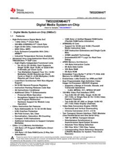
5 ADC INTERFACES The typical Analog -to-digital converter handles data in two basic operations shown in Figure 1. First, the ADC has a conversion period (tCONV) where it goes through its internal procedure to create a digital word that represents the voltage at its input. Second, the ADC transfers the acquired data word through a digital interface to a controller during the acquisition time (tACQ). The ADC will usually have a minimum cycle time (tCYC) before it can start another conversion that is about the sum of tCONV and tACQ but can be shorter when the ADC has special transfer modes that let acquisition and transfer overlap.
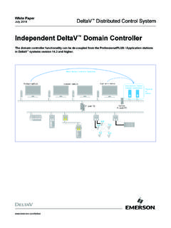
6 For simplicity, the following discussion will be based on sequential conversion and acquisition. Figure 1. Simple ADC Transfer Sequence The conversion time and minimum cycle time are the same no matter how the data is transferred. But the acquisition time depends on the properties of the data interface, in most cases the operation of the SPI bus. If the acquisition time is lengthened due to clock rates on the SPI, the sample rate of the ADC can be severely limited. SPI CLOCK RATE LIMITATIONS The SPI link between a microprocessor/FPGA (MCU) and an ADC is illustrated in Figure 2. The SPI bus consists of the connections between a pair of shift registers, one in the master MCU and one in the slave ADC.
7 The MCU provides a clock that synchronizes the transfer. One edge of the clock shifts data out of the shift registers and the complementary edge clocks the data that has been presented into the other end of each shift register in a ring topology. In the case of an ADC, there may not be a need to shift data from the MCU to the ADC so this channel has been eliminated for simplicity along with the slave select. The ADC fills its internal shift register during the conversion phase of Page 1 of 6 2014 Analog Devices , Inc. All rights reserved. MS-2689 Technical Article operation then shifts the register out during the acquisition phase.
8 Figure 2. ADC SPI Communication Block/Timing Diagram In an SPI transaction, the clock signal generated by the master travels to the slave through some wiring delays where it triggers the slave to shift out its data after some internal d e l ay. The data signal travels back to the master again through wiring delays where it must arrive at the master in time for the complementary edge of the clock. The master typically has some additional setup time requirements on this line. This timing is illustrated in Figure 2 and it shows that these delays establish the minimum time for half of a master clock period. In non isolated systems, these times are typically very short, in most cases <10 nS, and allow the SPI clock to run at speed in excess of 50 MHz.
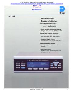
9 If an isolation barrier is added to the SPI data path, as shown in Figure 3, it adds terms similar to the trace delay. However, depending on the technology used for isolation, the signal propagation delay (prop delay, tpISO) through the isolation can be in excess of 100 nS. Figure 3 also shows how the new set of delay times extend the time required for a data transaction and significantly increase the half period of the SPI clock. The isolation delays dominate all other time delays in the system and the maximum clock frequency can drop to a few MHz. Figure 3. Isolated ADC SPI Communication Block/Timing Diagram The primary constraint on the clock period is the requirement that data is present at the master in time for the next clock edge.
10 In nonisolated systems this is not much of a constraint, and it actually adds to the robustness of the data transfer by allowing generous timing margins. However, once the propagation delay of the data path starts to dominate the half period, it severely degrades the maximum speed of the bus. Page 2 of 6 Technical Article MS-2689 Luckily there is a way around this limitation. If the data returning from the slave has an independent clock synchronized to it, a separate receiving shift register can be set up in the MCU to accept data based on the independent clock. In this case, the throughput of the SPI bus is no longer limited by the propagation delay of the isolation barrier, but by the throughput of the isolator.