Transcription of IT6810/IT6811/IT6812 IMPACT TRANSMITTER - Metrix …
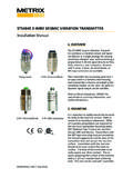
1 Doc# M9261 REV R(October 2020) Page 1 of 13 IT6810/IT6811/IT6812 IMPACT TRANSMITTER Installation ManualOVERVIEWThe Model IT6810/IT6811/IT6812 Im-pact TRANSMITTER uses new technology to measure IMPACT severity on reciprocating machinery. IMPACT is a proven method of detecting mechanical looseness on large reciprocating compressors. The IMPACT TRANSMITTER combines the benefits of this measurement with the convenience of 4-20 mA loop powered sensor technology. It has a built-in piezoelectric crystal sensing element, and uses a timing function as part of its severity determination.
2 An IMPACT event counter and memory device is used to record events meeting a preset amplitude threshold manual should be used by experienced personnel as a guide to the installation of the Model IT6810/IT6811/IT6812 IMPACT TRANSMITTER . Selection or installation of equipment should always be accompanied by competent technical assistance. We encourage you to contact the Metrix Instru-ment Co. or its local representative if you require further : Before proceeding to install and wire the TRANSMITTER , read and thoroughly understand these instructions.
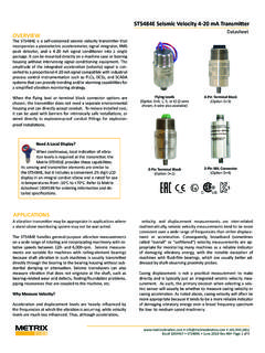
3 Confirm that the hazardous area rating of the TRANSMITTER meets or exceeds that of the area the unit is to be installed # M9261 REV R (October 2020) Page 2 of 13 MECHANICALM ounting LocationThe IMPACT TRANSMITTER is designed to detect mechanical looseness, not vibration. Therefore, it is mounted with its center bolt perpendicular to the direction of rod motion (figure 1), on top of the crosshead or extension piece, or for a power cylinder (figure 2) mounted on the side of the cylinder, where it will be out of the way of routine inspection or IMPACT TRANSMITTER includes both a 1/4-28 and a metric M6 x 1 threaded bolt.
4 Once threaded through the top half of the housing, the bolt becomes captive and will not inadver-tently fall out. It can be bolted to a machined surface, using a 9338 spot face kit, or it can be attached using an optional 1/4-18 NPT threaded adapter. Tighten or remove any loose items on or near the compressor cylinder. Never install on bolted covers or access doors. Since the IMPACT TRANSMITTER detects mechanical looseness, rattle noise from loose external parts can be mistaken for internal loose parts. This will result in false indications of compressor running condition.
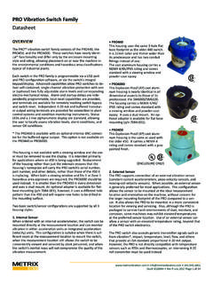
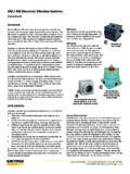
5 Ensure that the maximum ambient temperature is not IMPACT TRANSMITTER should be mounted such that the recommended baseline reading is 500 mV (rms) or less. For example, in Figure 1 the Separable compressor (engine separate from compressor ), the optimum location for mounting the IMPACT TRANSMITTER would be on the Crosshead, however, if the baseline reading is greater than 500 mV it is recommended to move the IMPACT TRANSMITTER to the Distance Piece as shown in Figure 1. For Integral Recip-rocating Compressors (engine is integrated with the compressor ), Figure 2, shows the typical mounting locations of the IMPACT Transmitters.
6 The same methodology for the Compression Cylinder is used for the Integral compressor as the Separable compressor . For the Power Cylinder the IMPACT TRANSMITTER should be mounted on the side of each cylinder, preferably in a location with a baseline reading of 500 mV or less, with height at the top of the travel of the wrist pin (see figure 2). In some applications locating the IMPACT Transmitters on top of each end of the cylinder banks has proven effective at identifying stuck engine & DIMENSIONSUNITS: mm [in]Aprox.
7 Weight: kg ( lbs)Refer to Metrix Datasheet 1009518 for specifications, ordering information, and # M9261 REV R(October 2020) Page 3 of 13 CrankshaftCrossheadIMPACT TRANSMITTER (Possible Locations)Distance PieceCompressorCylinderFigure 1: Sketch of a separable compressor cylinder showing IMPACT TRANSMITTER locationFigure 2: Sketch of an internal compressor cylinder and engine with IMPACT TRANSMITTER locationsMachined surfacePrepare a flat surface using an aircraft counter bore* with a minimum inch diameter and then tap the center hole for a -28 or M6 x 1 thread allowing for a minimum threaded depth of 3/8 inch (10mm).
8 The tapped hole must be perpendicular to the flat surface within degree. Apply a small amount of grease to the mating surface of the TRANSMITTER to allow for proper machine contact. With the connector pointed in a convenient direction, thread the appropriate mounting bolt through the housing and into the tapped hole. Torque the bolt to 75 inch-pounds maximum. NPT Threaded AdapterThis method allows a standard pipe thread to be drilled and tapped into the compressor body. The threaded adapter ( Metrix Part Number 9272) has the needed machined surface to insure proper mounting of the TRANSMITTER .
9 Install the TRANSMITTER as described in the previous housing for it6812 : The Metrix p/n 9288-XXX explosion-proof housing allows the TRANSMITTER to be installed into a Class I, Div. 1 (Groups B, C, D) area without the use of an intrinsically safe barrier. This housing is available from Metrix . Install the TRANSMITTER and housing in a similar manner as described in the previous sections.*Aircraft counter bores are available from most machine tool # M9261 REV R (October 2020) Page 4 of 13 WIRING DIAGRAM FOR NORMAL OPERATIONP ower SupplyMODELTERMINALCOLORIT6811 AWHITEIT6811 BBLACKIT6812 AREDIT6812 BBLACKI mpact TransmitterA 4-20mAB RLVDC Supply+-RL maximum = 50 /V (VDC-15V) Example: RL MAX = 50 /V (24V-15V) = 450 The connection to the TRANSMITTER can be made weather tight by using silicon grease in the connector.
10 ELECTRICALThe TRANSMITTER is a two-wire, 4-20 mA loop powered device and is wired like any other such field TRANSMITTER . One difference, however, is that rigid conduit cannot be connected directly to the TRANSMITTER . If conduit is required, use flexible conduit and provide a service loop to avoid any conduit strain on the TRANSMITTER . A simple wiring diagram is shown below. Typical input resistor values used in PLCs, monitors and DCS s are 50 W, 100 W or 250 W. The maximum resistance value that can be used in the current loop is a function of the supply voltage (VDC).