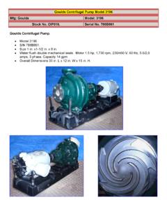
Transcription of ITT - GOULDS
1 GOULDS PumpsSSV G&L Series Repair PartsITTG oulds pumps is a brand of ITT Water Technology, Inc. - a subsidiary of ITT Industries, for lifeCommercial Water TABLE OF CONTENTSSSV MULTI-STAGESSV Product Line Numbering System ..3-4 Impellers and Intermediate bearings layout ..5 Bearings Position ..6 Coupling table ..71SV and SV Sectional view of pump ..81SV and SV List of repair parts ..93SV and 4SV Sectional view of pump ..103SV and 4SV List of repair parts ..1133SV and 46SV Sectional view of pump ..1 33SV and 46SV List of repair parts ..1366SV and 9 SV Sectional view of pump ..1466SV and 9 SV List of repair parts ..15 Horizontal Mounting options ..16 Victaulic connections ..16 Motor Adapter and Adapter Ring table ..17 Obsolete 5SV and 6SV Information ..18- 3 OPTIONSH = Horizontal Mounting AQ = Staging for Aquavar UnitsVic = Victaulic ConnectionsMECHANICAL SEAL OPTIONS 1SV 2SV 3SV 4SV 5SV / 6SV Code Rotary Stationary Elasto- 60 Hz 60 Hz 60 Hz 60 Hz 60 Hz 60 Hz 60 Hz 60 Hz 60 Hz No.
2 Mers (2-16 stg.) (18-22 stg.) (2-15 stg.) (16-22 stg.) (2-13 stg.) (14-16 stg.) (2-10 stg.) (12 stg.) (all) DPS (all) 50 Hz. (all) DPS (all) 50 Hz. (all) DPS (all) 50 Hz. (all) DPS (all) 50 Hz. (all) DPS (all) 50 Hz. (all) High 0 Temp Viton 10K93 10K113 10K93 10K113 10K94 10K114 10K94 10K114 10K95 10K95 Carbon 2 Silicon EPR 10K140 10K176 10K140 10K176 10K146 10K177 10K146 10K177 10K147 10K147 Carbide Silicon 4 Silicon Carbide Viton 10K99 10K178 10K99 10K178 10K100 10K179 10K100 10K179 10K101 10K101 Carbide High 6 Temp EPR 10K96 10K115 10K96 10K115 10K97 10K116 10K97 10K116 10K98 10K98 Carbon NUMBER OF STAGESF = 6 L = 11 R = 16 Z = 4B = G = 7 M = 1 S = 17C = 3 H = 8 N = 13 T = 18D = 4 J = 9 P = 14 V = 0E = 5 K = 10 Q = 15 X = DRIVER1 = 1PH, ODP 4 = 1 PH, TEFC 7 = 3 PH, XP 0 = 1 PH, XP = 3 PH, ODP 5 = 3 PH, TEFC 8 = 575 V, XP3 = 575 V, ODP 6 = 575 V, TEFC 9 = 3 PH.
3 TEFC Premium EfficiencyHP RATINGC = HP F = 1 HP J = 5 HP M = 15 HPD = HP G = HP K = 7 HP N = 0 HPE = 1 HP H = 3 HP L = 10 HP P = 5 HPHERTZ/RPM1 = 60 HZ, 3450 RPM, pole 5 = 60 HZ, 3500 RPM, 0-380V, = 60 HZ, 900 RPM, pole 6 = 60 HZ, 3500 RPM, 380V, V-Delta3 = 60 HZ, 3500 RPM, 380V 7 = 60 HZ, 1750 RPM, 08- 30/460V4 = 50 HZ, 900 RPM, 460 VMATERIAL AND SUCTION/DISCHARGEA = 304 Stainless Steel, in-line NPT threaded oval flange connections (1 3 SV only)B = 304 Stainless Steel, in-line ANSI flangeC = 304 Stainless Steel, top/bottom ANSI flange connectionsD = 316 Stainless Steel, in-line ANSI flangePRODUCT LINES tainless Steel VerticalNOMINAL FLOW1 = 15 GPM 3 = 55 GPM 5 = 145 GPM = 8 GPM 4 = 86 GPM 6 = 90 GPM1 4SV PRODUCT LINE NUMBERING SYSTEM 2 SV A 1 D 2 B 0 HThe various versions of the SSV line are identified by a product code number on the pump label. The number is also the catalog number for the pump.
4 The meaning of each digit in the product code is shown 92SV PRODUCT LINE NUMBERING SYSTEMThe various versions of the SSV line are identified by a product code number on the pump label. This number is also the catalog number for the pump. The meaning of each digit in the product code number is shown : Not all combinations are possible. Consult your G&L product codE33 SV B G 1 2 R 6 T A Hpump options (optional): H = Horizontal mounting D = High Pressure Pump (> 25 bar) Q= Service Factor Version (AQ) Seal options:motor Enclosure: D = ODP T = TEFC X = Explosion Proof P = TEFC Premium Effymotor Voltage: 1 = 115/230 2 = 230 only 3 = 230/460 4 = 460 only 5 = 575 6 = 208-230/460 7 = 200 8 = 190/380Hp rating: G = 2 HP M = 15 HP S = 50 HP H = 3 HP N = 20 HP T = 60 HP J = 5 HP P = 25 HP U = 75 HP K = 7 HP Q = 30 HP L = 10 HP R = 40 HPmotor Hertz/Speed/phase: 1 = 60 Hz/3500/1 2 = 60 Hz/3500/3 3 = 60 Hz/1750/1 4 = 60 Hz/1750/3 5 = 50 Hz/2900/1 6 = 50 Hz/2900/3 7 = 50 Hz/1450/1 8 = 50 Hz/1450/3 9 = 60 Hz/Variable/3 Number of reduced diameter Impellers (0, 1, 2) Bowls/Stages: A = 1 E = 5 J = 9 B = 2 F = 6 K = 10 C = 3 G = 7 D = 4 H = 8 Flange orientation: B = Cast Iron/316 stainless steel, in-line ANSI flange D = 316 stainless steel, in-line ANSI flangeproduct line.
5 Stainless Vertical Multi-StageNominal Flow: 33 = 150 GPM 66 = 350 GPM 46 = 225 GPM 92 = 450 GPM Code Rotary Stationary Elastomers Part Number No. 33SV 46SV 66SV 92SV A Carbon Viton 10L38 Mechanical B EPR 10L40 Seal C Silicon Carbide SiliconCarbide Viton 10L39 D EPR 10L37 Cartridge L Carbon Viton 10K163 Seal P Silicon Carbide EPR 10K1665 1 4SV IMPELLERS AND INTERMEDIATE BEARINGS LAYOUT 1SV 2SV 3SV 4SV Number Number Number of Number Number of Number Number of Number Number of of of Impellers in of Impellers in of Impellers in of Impellers in Stages Bearings Location Bearings Location Bearings Location Bearings Location A B C D E A B C D E A B C D A B C D 2 1 1 1 1 1 1 1 1 1 1 1 1 3 1 1 2 1 1 2 1 1 2 1 1 1 4 1 2 2 1 2 2 1 2 2 1 1 1 5 1 2 3 1 2 3 1 2 3 1 1 1 6 1 2 4 1 2 4 1 2 4 1 1 1 7 1 2 5 1 2 5 1 2 5 1 1 1 8 1 2 6 1 2 6 2 2 3 3 2 2 3 3 9 2 2 4 3 2 2 4 3 2 2 4 3 10 2 2 4 4 2 2 4 4 11 2 2 5 4 2 2 5 4 2 2 5 4 12 2 2 5 5 2 2 5 5 2 2 5 5 13 2 2 6 5 2 2 6 5 3 2 3 4 4 14 2 2 6 6 2 6 6 6 3 2 4 4 4 3 2 4 4 4 15 2 2 7 6 2 2 7 6 3 2 4 4 5 16 2 2 7 7 2 2 7 7 3 2 4 5 5 18
6 3 2 5 6 5 3 2 5 6 5 20 3 2 6 6 6 3 2 6 6 6 22 4 7 5 5 5 5 4 2 5 5 5 5 24 4 2 6 6 5 5 4 2 6 6 5 5 The chart on this page is used to locate the correct bearing position(s) on the impeller stack of the SSV series pumps . To use this chart: 1. Locate the number of stages in the left hand column of the above chart which corresponds to the pump you are working on.. Follow the selected row across to the pump size (1SV etc). 3. Under the A location, you will find the number of impellers on the bottom of the stack which come before the first bearing. 4. Under the B location, you will find the number of impellers which go above the first bearing and below the second bearing (if there is one). 5. Under the C location, you will find the number of impellers which go above the second bearing and below the third bearing (if there is one). 6. Under the D location, you will find the number of impellers which go above the third bearing.
7 6. Under the E location, you will find the number of impellers which go above the third of impellersLocation D BearingNumber of impellersLocation C BearingNumber of impellersLocation B BearingNumber of impellersLocation A Number of impellersLocation E Bearing6 BEARINGS POSITION Number of Stages Bearing Position Number of Diffuser with Bearing 1 2 3 4 5 N 2 6 N 2 7 N 3 1 8 N 4 9 N 5 10 N 2 and N 6 2SV 33 46 Number of Stages Bearing Position Number of Diffuser with Bearing 1 2 3 4 N 2 5 N 2 1 6 N 3SV 66 92 BEARINGBEARINGBEARINGBEARING7 COUPLING TABLE Item Pump Size Number of Stages No. 2 3 4 5 6 7 8 9 10 11 12 13 14 15 16 18 20 22 24 60 Hz TEFC 4L189 1SV ODP 4L188 4L188 4L189 50 Hz TEFC 4L188 ODP 60 Hz TEFC 4L189 4L189 SV ODP 4L188 4L189 50 Hz TEFC 4L188 4L189 ODP 60 Hz TEFC 4L193 3SV ODP 4L190 4L191 4L19 50 Hz TEFC 4L19 4L19 118 ODP 4L193 60 Hz TEFC 4SV ODP 4L191 4L19 4L193 50 Hz TEFC 4L193 4L193 4L193 ODP 60 Hz TEFC 5SV ODP 4L31 4L313 4L314 (obsolete) 50 Hz TEFC 4L314 ODP 60 Hz TEFC 6SV ODP 4L31 4L313 4L314 (obsolete)
8 50 Hz TEFC ODP COUPLING PIN SUPPLIED WITH COUPLING COMPLETE AND SHAFT ASSEMBLY Size Pin Repair Part Number 1SV 4L170 SV 3SV 4L171 4SV 33SV 46SV 4L83 66SV 9 SV 56C 180TC 210TC 250TC 280TC 320 TSC 360 TSC 1SV 4L188 4L189 2SV 3SV 4L190 4L191 4L192 4L193 4SV 5SV 4L312 4L313 4L314 6SV 33SV 46SV 4L553 4L554 4L555 4L556 66SV 92SV COUPLING GUARD (COMPLETE WITH HARDWARE) Pump Motor Frame 56C 180 TCH 180TC 210TC - 250TC 280TC 1SV 4L450 2SV 3SV 4L451 4L450 4L45 4SV 4L451 33-92SV 4L5158118159383258C524149150258349101240 5011225002965284084L242126258B443B199370 258A5401511004L247443A513174448358 1SV AND 2SV9 1SV AND 2SV Standard Staging - 50 Hz and 60 Hz (*50 Hz only) Reverse Stack sizes (60 Hz only) Item Part Name Pump Number of Stages Number of Stages No. 1SV 2 3 4 5 6 7 8 9 11 12 13 14 15 16 18* 20* 22* 24* 18 20 22 2SV 2 3 4 5 6 7 8 9 11 13 14 15 16* 18* 20* 22* 24* 16 18 20 22 240 Motor adapter See motor adapter chart page 17 501 Coupling guard See coupling guard chart page 7 Shaft assembly Type A 4L206 4L207 4L208 4L209 4L210 4L211 4L212 4L213 4L214 4L215 4L215 4L216 4L216 4L217 122 includes items Type B 4L206 4L207 4L208 4L209 4L210 4L211 4L212 4L213 4L214 4L215 4L215 4L216 4L216 4L217 4L431 4L432 4L433 4L434 4L217 4L431 4L432 4L433 149,199,370.
9 524 Type C 4L209 4L210 4L211 4L212 4L213 4L214 4L215 4L215 4L216 4L216 4L217 4L431 4L432 4L433 and coupling pin Type D 4L218 4L219 4L220 4L221 4L222 4L223 4L224 4L225 4L226 4L227 4L227 4L228 4L228 4L272 4L435 4L436 4L437 4L438 4L272 4L435 4L436 4L437 126 Shaft sleeve 4L180 Type A 1L344 1L345 1L346 1L347 1L348 1L349 1L350 1L351 1L387 1L353 1L353 1L354 1L354 1L367 100 Casing Type B 1L344 1L345 1L346 1L347 1L348 1L349 1L350 1L351 1L387 1L353 1L353 1L354 1L354 1L367 1L355 1L504 1L505 1L506 1L367 1L355 1L504 1L505 with fill plug Type C 1L368 1L369 1L370 1L371 1L372 1L373 1L374 1L374 1L375 1L375 1L352 1L652 1L653 1L654 Type D 1L356 1L357 1L358 1L359 1L360 1L361 1L362 1L363 1L364 1L365 1L365 1L366 1L366 1L390 1L507 1L508 1L509 1L510 1L390 1L507 1L508 1L509 Type A 4L172 151 Casing spacer Type B 4L172 Type C 4L172 Type D 4L250 513 O-ring casing 5L93 Viton (quantity 2) 5L88 EPR (quantity 2)
10 Type A 1L338 Pump body Type B 1L340 174 includes Type C1 1L342 item 151 Type D 1L388 Victaulic 1L500 1L449 Type A 1L379 Type B 1L380 448 Base plate Type C 1L380 Type D 1L380 Victaulic 1L379 Type A 1L377 159 Seal housing Type B 1L377 Type C 1L377 Type D 1L416 383 Mechanical seal with washer See mechanical seal option on page 3 524 Split ring 4L245 149 Split ring cover 4L243 Type A 4L174 258C Final spacer Type B 4L174 Type C 4L174 Type D 4L248 Type A 3L26 3L26 3L26 Final flange Type B 3L26 3L26 3L26 diffuser Type C 3L26 3L26 3L26 150 Type D 3L28 3L28 3L28 Type A 4L199 4L199 Final flange Type B 4L199 4L199 4L199 without diffuser Type C 4L199 4L199 Type D 4L422 4L422 4L422 Type A 4L198 4L198 Spacer sleeve, Type B 4L198 4L198 blank stage Type C 4L198 4L198 Type D 4L198 4L198 Type A Initial spacer Type B 4L448 Type C Type D 4L448 Type A 7L354 258A 1st stage bowl Type B 7L354 with o-ring (Viton) Type C 7L354 Type D 7L363 Type A 7L351 258B Bowl with bearing Type B 7L351 and o-ring (Viton) Type C 7L351 Type D 7L360 Type A 7L348 258 Bowl with Type B 7L348 o-ring (Viton) Type C 7L348 Type D 7L357 349 O-ring (impeller) 5L90 (Viton) 5L83 (EPR) 101 Impeller 1SV = 2L160 2SV = 2L170 443A Impeller spacer 4L177 443B Impeller spacer (intermediate) 4L176 199 Impeller washer (spacer) 13L105 4L449 370 Impeller screw 13L95 500 Tie rod with nuts and washers 4L230 4L231 4L232 4L233 4L234 4L235 4L236 4L237 4L238 4L239 4L239 4L240 4L240 4L273 4L322 4L323 4L324 4L325 4L273 4L322 4L323 4L324 296 Nut, tie rod 13L98 528 Washer, tie rod 13L100 540 Oval flange assembly 1SV = 4L185 2SV = 4L186 118 Coupling assembly See coupling table on page 5 408 Fill plug with o-ring 6L19 Viton 6L25 EPR 358 Drain plug with o-ring 6L17 Viton 6L23 EPR Shim, coupling 4L242 Fill funnel 4L247 NOTE.