Transcription of Jamming on X- Band Radar - IOSR-JEN
1 IOSR Journal of Engineering (IOSRJEN) ISSN (e): 2250-3021, ISSN (p): 2278-8719 Vol. 04, Issue 04 (April. 2014), ||V2|| PP 08-12 International organization of Scientific Research 8 | P a g e Jamming on X- Band Radar Mahmoud Yahia Hussein, AbdelrasoulJabar Alzubaidi 1, Department Of Electronics Engineering, 1 SudanAcademy Of Sciences 2,Electronics Engineering School, Sudan University Of science And technology Abstract: - Radar Jamming is the intentional emission of radio frequency signals to interfere with the operation of a Radar by saturating its receiver with noise or false information. In this paper Jamming technique is used to jam x-band Radar frequency. To accomplish this goal it's proposed to design circuit using Basic Stamp, ATmega16 Microcontroller, two X-Band motion detector modules, LCD and Digi's X-CTU software. In this design we considered one of x-band motion detector module as a Radar and the second x-band motion detector as jammer circuit which uses Doppler frequency principle and generates GHZ frequency.
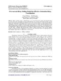
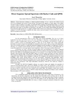
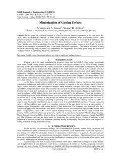
2 Keywords: - Radar , Jamming , Basic stamp2, X-band motion detector, Antenna, Doppler I. INTRODUCTION Electronic warfare (EW) is the art and science of denying enemy forces from use the electromagnetic spectrum in our space. While preserving its use for friendly forces and it is a significant force multiplier because reduces friendly losses by defeating or reducing the effectiveness of enemy weapons. As shown in Figure 1 EW is commonly divided into three subfields: a. Electronic Support (ES) Involves receiving enemy signals to identify and locate threat emitters and to help determine the enemy's force structure and deployment. b. Electronic Attack (EA) Involves measures taken to defeat enemy electronic assets. It includes Jamming , chaff, directed energy weapons, and anti radiation missiles. c. Electronic Protection (EP) Comprises countermeasures to enemy electronic attack. All of these concepts are applied at Radar , communication, infrared, and laser operating system.
3 In our study we concerned on electronic attack using Jamming technique to denying enemy forces from use the electromagnetic spectrum in our space. To accomplish this objective, both offensive electronic attack (EA) and defensive electronic protection (EP) action are required. Electronic attack involves Defense forces and platforms against hostile weapon, and C3 (command, control and communication) systems .Electronic attack is a division of electronic warfare involving the use of electromagnetic energy, directed energy, or anti radiation weapons to attack personnel, facilities, or equipment with the intent of degrading, neutralizing, or destroying enemy combat capability and is considered a form of fires. II. METHODOLOGY Design of a Radar Jamming circuit consists of two parts: A. Hardware components: microcontrollers AT mega (16) Electronic Warfare Electronic Protection Electronic Attack Electronic Support Figure 1: Components of EW Jamming on X- Band Radar International organization of Scientific Research 9 | P a g e The ATmega16A is a low-power CMOS 8-bit microcontroller based on the AVR enhanced RISC architecture.
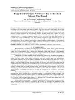
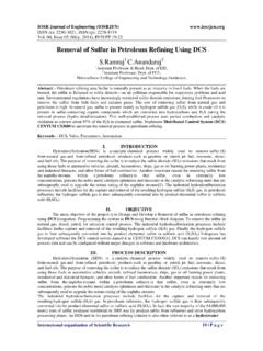
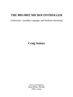
4 By executing powerful instructions in a single clock cycle, the ATmega16A achieves throughputs approaching 1 MIPS per MHz allowing the system designer to optimize power consumption versus processing speed. The ATmega16 AVR is supported with a full suite of program and system development tools including: C compilers, macro assemblers, program debugger/simulators, in-circuit emulators, and evaluation kits a microcontroller makes highly-accurate measurements of the frequency, which it displays on an LCD. The microcontroller also has a serial (RS232) interface that allows connection to a PC. X Band Motion Detector The X Band Motion Detector is a common ingredient in security systems it s a Doppler Radar sensor that operates in the X-band frequency at GHz, and indicates movements with oscillations in its high/low out put. The X Band Motion Sensor is constructed of two boards connected by posts: a control board, and the antenna PCB with the Doppler sensor. When the enable pin is either held high or left floating, the control board cycles the Doppler sensor s power at 2 kHz, 4% duty cycle.
5 The Doppler sensor s GHz oscillator signal is routed to the Tx antenna, and also to a mixer diode. The mixer diode s IF output contains signals with the sum and difference of the transmitted and received frequencies along with components of the original signal and some harmonics. Operation of x-band motion detector The difference signal s frequency that results from mixing the outgoing and returning signal frequencies is the important component. It oscillates at a frequency corresponding to how much the returning signal has been either compressed or stretched as a result of the Doppler Effect that an object has on the signal as the object moves toward or away from the sensor .The difference signal s frequency is related to the component of the object s speed toward or away from the sensor by this equation: Where: Fd = Difference frequency (sometimes referred to as Doppler frequency) V = Velocity of the target, Ft = Transmit frequency c = Speed of light at 3 108 m/s, = Motion direction angle BASIC Stamp The BASIC Stamp Home Work Board is ideal for learning circuits, electronics, and microcontroller programming.
6 The solder less breadboard makes it easy to connect 5 V compatible sensors, displays, LEDs, and other electronic components to create the different inventions. Program in PBASIC, which is flexible to read and learn. It is an ideal "first-time" programming language, with many built-in commands that simplify interfacing to other devices. microcontrollers are frequently used device in embedded computing in which the application varies from computing, calculating, smart decision-making capabilities, and processes the data. Most of the electrical/electronic device, sensors and high-tech gadget can be easily interface and interact with microcontrollers to automate a system structure. The microcontroller has a serial (RS232) interface that allows connection to a PC. The microcontroller will stream the data a PC over the serial link. The PC will capture the Figure 2: x-band motion detector Fd = 2V Ft cos .. (1) c Jamming on X- Band Radar International organization of Scientific Research 10 | P a g e software using terminal-emulation software.
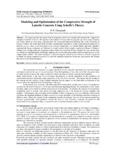
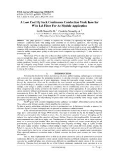
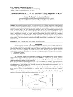
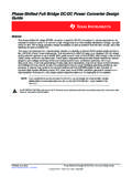
7 The microcontroller will stream the measured line frequency to the PC over the serial link. Circuit design The Radar Jamming design concept for this research is divided into two parts as shown in Figure 3. B. Software It is assumed that the number of pulses represent the range to the target .The principle of algorithm in figure 5 is based on comparing the number of pulses received by x-band module .If the number of pulses detected differs then expect it .if the same is detected Jamming takes place. Figure 3: Block diagram for Radar Jamming system Jamming on X- Band Radar International organization of Scientific Research 11 | P a g e III. RESULT According to the block diagram in figure 3, the Jamming module affects on the operation of the Radar module (x-band motion detector).As illustrated in table 1 the number of pulses (values) differ when the x-band module is jammed.
8 Table 1: Out put of x-band motion detector Normal detected pulses (values) Jamming detected pulses comments 5 3 Jamming occurred 11 6 Jamming occurred 17 9 Jamming occurred 0 0 No pulses IV. CONCLUSION From the results, use an active jammer technique is denying the use of the Radar spectrum successfully. It depends on many factors, including the distance between the Radar and the jammer. The system also requires evaluations that focus on the behavior of the operators of the victim systems. The specific RF output of the technique should be measured to ensure that the frequency, timing, amplitude, and pulse characteristics are consistent with the intended Jamming technique. REFERENCES [1] Merrill I. Skolnik, Introduction to Radar system , second ed. UnitedState, McGraw-Hill, lnc, 980. P: 7, 19, 23, 47-56,152,226,227,460. Jamming on X- Band Radar International organization of Scientific Research 12 | P a g e [2] Richard , Introduction to Communication electronic warfare system , , Artech House, 2002, P: 189,449,509.
9 [3] Basic Stamp 2 microcontrollers comparisons. Retrieved April 28, 2012 from website of Parallax. Inc. developer and distributor of Basic Stamp 2 microcontroller . [4] [5] Mugu, Electronic warfare and Radar systems Engineering Handbook , Washington , April 1999, section , , , [6] Martin Welch, Electronic Warfare Technical Expert , 771 TS/EWAP,30 Hoglan Avenue Edwards AFB, CA93524, USA,2012 [7] Mike Pywell, Electronic Warfare Technologist , Warton, PrestonPR4 1AX,UK,2012 [8] Mourad Barkal, Signal Detection and Estimation , Second edition, Boston/London,Artech House, 2005, P: 99-105, 348.