Transcription of Jet Engines – Bearings, Seals and Oil Consumption
1 1 Memo Date: 2018-04-02 Prof. Dr. Dieter Scholz, MSME Aircraft Design and Systems Group (AERO) Department Automotive and Aeronautical Engineering Hamburg University of Applied Sciences Hamburg Berliner Tor 9, 20099 Hamburg, Germany Phone: +49 - 40 - 42875 - 8825 E-Mail: WWW: Download from: Jet Engines Bearings, Seals and Oil Consumption Abstract Purpose of this review is to understand how to find values for three input values for the calculation of the oil concentration in aircraft cabins. These are the number of bearings of the jet engine and the number of them upstream of the bleed air ports as well as the oil Consumption per hour. Methodology is an Internet review of related facts. Findings: Jet engine schematics are available online and can be interpreted to find the number of bearings.
2 Values for the CFM56 engine are 5 bearings with 3 of them upstream of the bleed port. Oil Consumption should be assumed to be L/h for the CFM56 engine. Rates for selected other Engines are also given. Research limitations are due to the fact that detailed company data is not available and own measurements can not be made on passenger jets. 2 1 Introduction An attempt has been made to estimate the amount of oil leaving a jet engine into the bleed air. Bleed air is air taken from the engine compressor. It is used (among other tasks) for aircraft cabin air conditioning. In order to perform this calculation some jet engine parameters have to be known (Scholz 2017): number of engine bearings, number of bearings upstream of the first bleed port, engine oil Consumption per flight hour.
3 This memo tries to provide these numbers. The method of investigation is a review of available information provided through the Internet. Bearings are used to support engine shafts/rotos. Bearings are lubricated inside a bearing sump, which is sealed. Often labyrinth type Seals are used together with air, which is also holding back the oil. Air and oil have to be separated and the air is eventually vented over board. Some oil is lost along various paths causing oil Consumption . Only oil lost through bearing Seals upstream of the bleed ports can contaminate the bleed air. Chapters 2, 3 and 4 look at (the number of) engine bearings, their lubrication in a sump, its Seals and the lubrication system of a jet engine as a whole. Focus is also on the mechanisms of oil losses.
4 Chapter 5 shows the position of the bleed ports in the high pressure compressor and their position with respect to the bearings with their potential oil losses. Chapter 6 summarizes numerical values (in qt/h) collected of jet engine oil Consumption . Details from the Internet are given in the Appendix. Chapter 7 looks at oil Consumption monitoring to understand where these numerical values come from. 2 Jet Engine Shafts and Bearings Main jet engine shafts are supported by a minimum of two bearings. At least one bearing has to be a thrust ball bearing that can take axial and radial loads. The other bearing can be a cylinder roller bearing that takes only radial loads. Bearings are located inside a bearing sump. "Oil sumps are part of the oil circuit, where oil must remain.
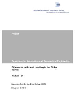
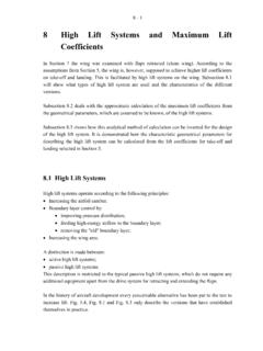
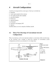
5 Leakage outside the oil system could pollute the air bleeds or result in an engine fire." Two or more oil sumps are distributed along the engine shaft. (Exxon 2016b) 3 Bearings of the CFM56 engine are shown in Figure 1. The engine has 2 shafts called HP shaft and LP shaft. The rotors (shafts and discs) are supported by 5 bearings mounted in two engine sumps for lubrication. The engine rotors are supported by two frames via the bearings. The forward sump is in the fan frame and is the location of bearings No. 1, No. 2 (fan/booster shaft) and No. 3 (HP shaft forward part). The aft sump is in the turbine rear frame where bearings No. 4 (HP shaft aft part) and No. 5 (LP shaft aft part) are located. Seals of various types are provided to confine the oil.
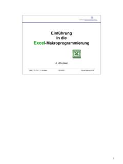
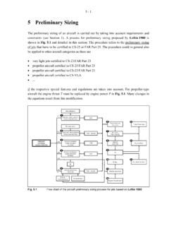
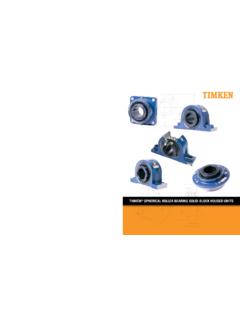
6 Pumps for oil supply, oil scavenge, seal pressurization and sump vent subsystems produce a system known as a dry sump. Engine sumps are vented to ambient pressure. (Lufthansa 1999) Note: bearing number 3 consists of a double bearing . In numbering the bearings, it is considered as one bearing . Bearings of the Rolls-Royce Trent 1000 engine are shown in Figure 2. The engine is used on the Boeing 787. Trent 1000 is a bleedless design, with shaft power off-takes from the IP shaft instead of the HP shaft found in other members of the Trent family. (Wikipedia 2018a). As a bleedless engine the Rolls-Royce Trent 1000 only serves here only as a further example of engine ( bearing ) technology. The engine has 3 shafts called LP, IP and HP shaft. The shafts are supported by 8 bearings as detailed in Figure 2.
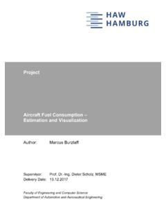
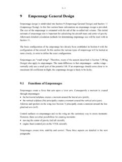
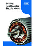
7 The 4 bearing chambers are: the front bearing housing (FBH) at the front of the engine; the internal gearbox (IGB), towards the centre of the engine; the HP-IP bearing chamber also towards the centre of the engine and the tail bearing house (TBH) towards the rear of the engine. Of these the two hottest chambers are those in the middle of the engine. Figure 3 shows the complicated air sealing in the HP-IP hub. (Ademiyi 2015) Figure 1: Location of the 5 bearings of the CFM56 engine (Lufthansa 1999) 4 Figure 2: Location of the 8 bearings of the Rolls-Royce Trent 1000 engine (Ademiyi 2015) Figure 3: Details of HP/IP bearing chamber with two cylinder roller bearings of the Rolls-Royce Trent 1000 engine (Ademiyi 2015) 5 3 bearing Sumps Sumps are sealed usually by labyrinth Seals .
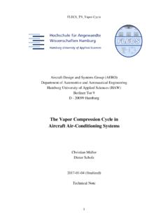
8 Less often carbon Seals or brush Seals are used. A sump (called a "wet cavity") with labyrinth type Seals in hot areas (typically mid-sumps) are usually surrounded by a "dry cavity" that is sealed by a second labyrinth type seal. In this way a double wall design is achieved (Figure 4). Pressurized air enters the dry cavity and moves from the outside to the inside of the wet cavity to hold back the oil in the labyrinth seal. The air mixes with the oil in the sump (wet cavity) producing an oil mist (air and oil mixture). The oil mist is directed to an air/oil separator. (Exxon 2016b) "The separation of the [scavenge] oil and air first occurs in the de-aerator. After [that] the mixture .. [is] sent to the centrifugal breather for further separation. Once the oil is separated from the air, the oil is sent back into the bearing chambers and gearboxes to provide lubrication, while the air is vented from the system.
9 " "Separating the oil and air is necessary because by separating the oil and air, the amount of oil that is vented outside the engine is minimized." (Hehir 2016) Four different flows with an air/oil mixure need to be differentiated (see Figure 4): 1. The 'oil out to scavenge pumps' contains some air bubbles. This air has to be removed in a de-aerator located on the oil tank (Figure 5). 2. The 'vent to de-oiler' is an air/oil mist. The de-oiler can be an individual one for the bearing sump or it can lead to a central de-oiler as shown in Figure 6 and 7. 3. The 'drain (oil)' consist predominantly of oil. "In many applications, oil that crosses the [inner] oil seal is [drained,] collected and routed by a tube to an aircraft drain collector that is inspected from time to time and is used as a seal monitoring tool.
10 " (Exxon 2016b) 4. The 'Air & Oil' out the air seal consists predominantly of air, but some oil is also present as indicated in Figure 4. This flow enters the compressor. It is important "to avoid [oil] leaks due to too low p through the oil Seals ." The differential pressure p across the oil seal is the difference between the pressurized air entering the dry cavity (equal to the pressure in the compressor) and the vent pressure. "The vent tube must remain wide open" to ambient air (at ambient pressure) to achieve low enough vent pressure for sufficient p. In other words, "to be leak free [and to enable the flow of air into the wet cavity (to hold back the oil)], the pressure must always remain lower inside than outside the sumps." (Exxon 2016b) 6 Figure 4: Typical bearing lubrication and sealing in a jet engine.