Transcription of Jim Brown K9YC Santa Cruz, CA http://k9yc
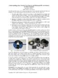
1 coaxial transmitting ChokesJim Brown K9 YCSanta Cruz, Don t Bother Taking NotesThese slides (and a lot more) are at \ Why Do We Need chokes ? Understanding Common Mode and Differential Mode Currents on Transmission Lines Differential Mode Current Transmission line carrying power from transmitter to antenna, or from antenna to receiver Signal is voltage between the two conductors Current flows out on one conductor and returns on the other Currents are equal and opposite in polarity II Differential Mode Current Transmission line carrying power from transmitter to antenna, or from antenna to receiver Signal is voltage between the two conductors Current flows out on one conductor and returns on the other Field exists between the two conductors No radiation from ideal line At a distance, field of one conductor cancels field of the other conductor Differential Mode Current Currents are equal and opposite in polarity Field mostly between the two conductors No distant radiation from ideal line At great distance, field of one conductor cancels field of the other conductor In the near field of an ideal line, the fields do not cancel Most observers will be slightly closer to one conductor than the other, so cancellation will not be perfect Common Mode Current Equal and flowing in the same direction on all conductors of the transmission line Current flows lengthwise on the line No cancellation of one current by another.
2 Because they re in polarity Line acts as long wire antenna It radiates and it receives Common ModeCommon ModeIt s an Antenna Common ModeCommon ModeIt s an AntennaThis feedline carries both differential and common mode current Ham Antennas and Balance Most ham antennas are unbalanced by their surroundings, even when fed by a balanced source and line What Makes a Circuit Balanced? What Makes a Circuit Balanced? The impedances of each conductor to the reference plane are equal Balance is not defined by voltage or current Imbalance impedances cause unbalanced currents Ham Antennas and Balance Most ham antennas are unbalanced by their surroundings, even when fed by a balanced source and line Unequal capacitances to nearby conductors Unequal inductive coupling to nearby conductors Trees, buildings, towers, terrain Feedline comes off at an angle Coax is not a part of these imbalances Common ModeCommon Mode Common Mode Common Mode Current Unbalanced Antennas and Lines If the antenna is unbalanced Unequal voltage and current to earth Unequal currents on the feedline The difference is common mode current, and it radiates from the line Coax did not cause the imbalance in these antennas!
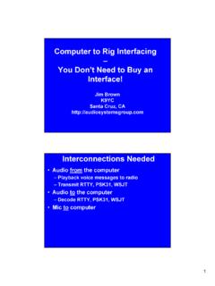
3 Coax simply adds to the imbalance The Fields around Coax and Twinlead are Very Different Coax is Special All the differential power (and field) is confined inside the coax All the common mode power (and field) is outside the coax A ferrite core surrounding coax sees only the common mode power (and field) No differential mode radiation Coax is Special Skin effect splits the shield into two conductors Inner skin carries differential mode current (the transmitter power) Outer skin carries common mode current (the current due to imbalance) Now We Can Talk About Common Mode chokes ! What s a Common Mode Choke? A circuit element that reduces common mode current by adding a high impedance in series with the common mode circuit Reduces radiation from the cable Reduces reception by the cable Some Common Mode chokes A coil of coax at the antenna A string of ferrite beads around coax (Walt Maxwell, W2DU) Multiple turns of transmission line through a toroid (Joe Reisert, W1JR) or stack of toroids (W1 HIS, K9YC) Most 1:1 baluns are common mode chokes chokes you can buy (W2DU, W0 IYH Baluns) 4 turns RG8 7 turns RG8X 5 turns Big Clamp-On RG8X 5 turns RG8 Much better chokes you can build Much better chokes you can build Some Common Mode chokes Some 2:1, 3:1, and 4:1 baluns are also common mode chokes Guanella balun But the few I ve measured aren t very good common mode chokes Why transmitting chokes ?
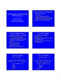
4 Isolate antenna from its feedline Reduce receive noise Keep RF out of the shack (and your neighbor s living room stereo) Minimize antenna interaction Field Day, CQP Expeditions SO2R, Multi-multi Dipole feedline and vertical antenna Common Mode CurrentRF in the ShackReceive Noise Design of transmitting chokes Higher impedance is better! Reduces common mode current Reduces noise Reduces interaction Reduces RF in the shack Reduces dissipation Resistance is better than reactance Why is Resistance Better? We want to reduce the current A cable shorter than /4 is capacitive Series inductance resonates with it and increases the current A cable longer than /4 (and shorter than 3 /4) is inductive Series capacitance resonates with it and increases the current Resistance always reduces current Why is a Simple Coil of Coax a Lousy Choke? Because it s just an inductor Can resonate with the line and increase the current Will resonate with its own stray capacitance (between turns) Above resonance it s a capacitor Can resonate with the line and increase the current Ferrite chokes are the Answer!
5 Why is Fair-Rite My Example ? Their published data is FAR better than any of their competitors You can study it and understand How ferrites work How one part is different from another How one mix is different from another How each part will work in your circuit The numbers I m using are those that describe parts made by Fair-Rite Why Is Fair-Rite My Example? Most ferrites sold by ham distributors are actually made by Fair-Rite Ham distributors charge HUGE markups (typically 5X their cost) Palomar, Amidon, Wireman, DX Engineering, etc. Industrial distributors don t! Allied, Newark, Lodestone Pacific, Digikey, Dexter Magnetics, Kreger Why Is Fair-Rite My Example? They re a great company to deal with Their parts are the most useful for ham applications They are easy to buy in North America Stick to the industrial distributors What s a Ferrite?
6 A ceramic consisting of an iron oxide manganese-zinc nickel-zinc Has permeability ( ) much greater than air Better path for magnetic flux than air Multiplies inductance of a wire passed through it Is increasingly lossy at higher frequencies sizes and shapes What s Do the Numbers Mean? The MIX the chemical formula of the iron oxide! A ceramic consisting of an iron oxide manganese-zinc (MnZn) 1-30 MHz (AM broadcast, hams) #31, #77, #78 nickel-zinc (NiZn) 30 MHz-1 GHz (FM, TV, cell phones) #43, #61, #67 #31 is a new MnZn mix that behaves like #43 at HF and VHF, but is much better below 5 MHz A simple equivalent circuit of a wire passing through a ferrite Rs and Xs vary with frequency!#31 Parallel Resonance!1 MHz10 MHz100 MHz1 GHz Rs and Xs vary with frequency!#31 Parallel Resonance!1 MHz10 MHz100 MHz1 GHz A Ferrite for UHF SuppressionParallel Resonance!
7 #611 MHz10 MHz100 MHz1 GHz Equivalent Circuit of a Ferrite ChokeLow FrequenciesMid-Frequencies____High Frequencies More General Equivalent Circuit____Including Dimensional Resonance (more than we have time to talk about today) We ll Use This Physical Equivalent Circuit to Understand the Choke____Data Sheets Use This Equivalent Circuit to Graph the Impedance Rs and Xs vary with frequency!#31 Parallel Resonance!1 MHz10 MHz100 MHz1 GHz Where s the Capacitance here? From the wire at one end of the choke to the wire at the other end, through the permittivity of the ferrite (it is a dielectric!)Where s the Capacitance here? Strings of Beads (W2DU, W0 IYH Baluns) A String of Different Beads Small bead used in W2DU Choke1 MHz10 MHz100 MHz1 GHzHF BandsXC W2DU Choke A string of beads choke Impedances in series add 50 beads = 50 x Z of one bead W2DU used #73 mix (a very good choice) Increasingly resistive above 3 MHz Less sensitive to feedline length Much better than bead of W0 IYH choke Many more beads are needed They re small and cheap (good) #73 only made to fit RG58 or RG303 InductiveCapacitiveResistiveChoke is 10 long Newer (Poor) Designs W2DU s design is 40 years old That s old fashioned -- certainly something newer must be better!
8 W2DU s beads are tiny W0 IYH tried something bigger BIG beads that fit on RG8 #43 Bead used in W0 IYH Choke1 MHz10 MHz100 MHz1 GHz HF BandsInductive W0 IYH Choke Also a string of beads choke Predominantly inductive below 25 MHz Very sensitive to feedline length Inductance resonates with a capacitive line Increasingly resistive above 25 MHz Much less sensitive to feedline length Not very effective below 15 meters! A #31 Bead for the String1 MHz10 MHz100 MHz1 GHz(Fits RG8)HF BandsInductive1 x long Using #31 Beads in the String1 ft long(2 ft)(4 ft)And it s Inductive! (Bad) InductiveCapacitiveResistiveChoke is 10 long Using #31 Beads in the String1 ft long(2 ft)(4 ft)And it s Inductive! (Bad) Some Commercial Products(Not Measured From Datasheet)Inductive (BAD) There s A Much Better Way to get Higher Impedance Inductance increases as N2 Inductively coupled resistance increases as N2 Measured Data for #43 Toroid ChokesThe Power of N2 !
9 2x=4x2x=4x30120480 HP8753C w/HP85046A S-parameter Test Set(by my anonymous collaborator) Why the Resonance Moves Down Inductance increases as N2 Inductively coupled resistance increases as N2 Capacitance increases with N Capacitance between turns Capacitance through the ferrite core A bit more capacitance with much bigger wire (like coax) The Power of Turns at HF and MF Moves the resonance down from VHF to HF More inductance More capacitance Multiplies impedance at resonance But not by N2, because resonance has moved lower in frequency Measured Data for #43 Toroid chokes Measured Data for #31 Toroid chokes 4 turns RG8 7 turns RG8X 5 turns Big Clamp-On RG8X 5 turns RG8 K9YC chokes (Improvements on W1JR, W2DU Designs) The Big Clamp-On When You Can t Easily Take the Connector Off Wide or Close Spaced Turns? Close spacing lowers resonant frequency More capacitance More inductance Close spacing often better below 10 MHz Wide spacing usually best above 10 MHz Study the K9YC data and Cookbook for specific applications Let s Talk About Dissipation(Heat, Power Handling) Dissipation and Form Factor 1,500 W in 50 ohms = 275V @ PEP Heat produced by the average power With CW, ~ 3 dB less than PEP SSB without speech processing or clipping ~ 14 dB less than PEP SSB with heavy processing ~ 6 dB less than PEP Most power amps must be de-rated by 3 dB for RTTY, PSK, FM, AM Dissipation and Duty Cycle We ve got to listen sometime, so subtract another 3 dB (50% listening)
10 Real world average ham power levels for intense contesting and DXing ~ 6 dB less than PEP for CW ~ 9 dB less than PEP for SSB ~ 6 dB less than PEP for RTTY, PSK, FM Heat in Common Mode chokes Heat (Power) is I2 R I and R are common mode values Make R very large I falls in proportion to R P falls as I2 so power (heat) falls twice as fast as R increases Obtain current from the NEC model of the common mode circuit What About Heat? Heat is not a problem in coax chokes if R (the choking impedance) is large enough How large is enough? For a reasonably well matched antenna with reasonably good balance, R = 5,000 ohms keeps dissipation low Failures From Excessive Voltage P = E2 / R Causes of excessive voltage Antenna systems that make E very large Feedline length near /2, , 3 /2, 2 , etc. Antenna tuners that step voltage up to high impedance lines Severe imbalance Let s study an example in NEC A Real Antenna, Unbalanced NEC Model of 40M dipole, fed by 67 ft of coax (half wave), 5,000 ohm choke (Vf ~ for common mode)PEPC onstant CQingLegs (Ft)PowerVoltsCW, FM, RTTY, PSKSSB30 - 3630 W387 V8 W4 W27 - 3980 W632 V24 W12 W24 - 42150 W866 V40 W20 W20 - 46253 W1125 V80 W40 W chokes Exposed to Air Flow Can Handle More Power A choke in a closed box is much more likely to overheat Causes of Choke Failures Feedline near /2 combined with strong antenna imbalance Insufficient air circulation Choking impedance too low How Much Choking Z is Enough?