Transcription of JIS G3454 Carbon Steel Pipes for Pressure Service
1 Global Marketing for Tube & pipe JIS G3454 Carbon Steel Pipes for Pressure Service 1. Scope This japanese industrial Standard specifies the Carbon Steel Pipes , hereinafter referred to as the " Pipes ", used for Pressure Service at an approximate maximum temperature of 350 C. The Pipes for high Pressure Service shall be in accordance with JIS G 3455. Remarks 1. Pertaining to the electric-resistance welded Steel tubes, when previously agreed upon with the manufacturer, the purchaser may designate the supplementary quality requirements Z 3 or Z 4 specified in Appendix, in addition to the items specified in this text.
2 Appendix Z 3 Ultrasonic Examination Appendix Z 4 Eddy Current Examination 2. The units and numerical values given in { } in this Standard are based on the international System of Units (SI) and are appended for informative reference. Further, the traditional units accompanied by numerical values in this Standard shall be converted to the SI units and numerical values on Jan. 1, 1991. 2. Grade and Designation The pipe shall be classified into two grades and their letter symbols shall be as given in Table 1-1 or Table 1-2.
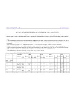
3 Table1 Letter symbol of grade (Informative reference) Traditional letter symbol of glade STPG 370 STPG 38 STPG 410 STPG 42 World standard comparative table KS ASTM JIS DIN BS Grade Number GRADE Grade Number GRADE Grade Number GRADE Grade Number GRADE Grade Number GRADE D 3562 SPPS 370 SPPS 38 A 53 A 135 Gr A Gr A G-3454 STPG 370 (STPG 38) 1626 1628 1629 1630 17172 St St St St 3601 778 ERW 360 S 360 HFS 22 CDS 22 ERW 22 Global Marketing for Tube & pipe SPPS 410 SPPS 42 A 53 A 135 Gr B Gr B STPG 410 (STPG 42) 1626 1628 1629 1630 17172 St St St St 3601 ERW 360 S 360 HFS 27 CDS 27 ERW 27 API Grade Number GRADE Gr A Gr B 5L X 42 X 52 X 56 X 60 X 65 X 70 X 80 3.
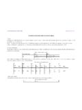
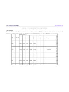
4 Method of Manufacture. The Method of manufacture shall be as follows: The pipe shall be manufactured by either the seamless of the electric resistance welding process. (Applicable till the end of 1990) The pipe shall stay as manufactured. However, the cold- finished Steel pipe shall be annealed after manufacture. The purchaser may specify heat treatment for the weld of the electric resistance welded Steel pipe of grade STPG 42, as necessary. When required by the purchaser, the pipe may be furnished with a becwl end(1) Note (1) Unless otherwise specified, the shape of the bevel end shall be as shown in Fig.
5 1. Global Marketing for Tube & pipe 4. Chemical Composition The pipe shall be tested in accordance with and the ladle analysis values obtained shall conform to Table 2-1 or Table 2-2. Table 2 Elongation % Letter symbol of grade C Si Mn P S STPG 370 max. max. to max. max. STPG 410 max. max. to max. max. 5. Mechanical Properties Tensile Strength, Yield Point or Proof Stress and Elongation The pipe shall be tested in accordance with and the tensile strength, yield point or proof stress and elongation obtained shall comply with Table 3-1 Table 3 Mechanical Properties Tensile strength Yield point or proof stress Elongation % and test pieces No.
6 5 test pieces No. 4 test piece Letter symbol of grade kgf/mm2 {N/mm2} kgf/mm2 {N/mm2} Longitudinal Transverse Longitudinal Transverse STPG 370 38 {373}min 22{216} min 30 min 25 min 23 min 28 min STPG 410 42{412}min 25{245} min 25 min 20 min 19 min 24 min Remarks. Global Marketing for Tube & pipe 1. When the tensile test is carried out for No. 12 or test piece for the pipe under 8mm in wall thickness, the minimum value of elongation shall be obtained by subtracting from the values of elongation given in Table 3-1 for each 1 mm decrease in wall thickness, and rounding off to an integer in accordance with JIS Z 8401.
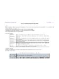
7 Examples of calculation are given in Informative Reference Table1. 2. The values of elongation given in Table 3-1 shall not be applied to the pipe whose nominal diameter is 25A or smaller. However, the value of elongation shall be recorded. 3. In sampling the tensile test pieces from the electric resistance welded Steel pipe , or test piece shall be taken from the portion not involving welded seams. Informative Reference Table 1. Examples of Elongation Values Calculated for test piece (longitudinal) and test piece (transverse)taken from Pipes under 8mm in wall thickness Elongation value relating to wall thickness % Letter symbol of grade shape of test piece Over 7mm to and Over 6mm to and excl7mm Over 5mm to and Over 4mm to and excl.
8 5mm Over 3mm to and excl. 4mm Over 2mm to and excl. 3mm Over 1mm to and excl. 2mm No12 test piece 30 28 27 26 24 22 21 STPG 370 No5. test piece 25 24 22 20 19 18 16 No. 12 test piece 25 24 22 20 19 18 16 STPG 410 No 5. test piece 20 18 17 16 14 12 11 Flatness When tested in accordance with , the pipe shall not generate flaws of cracks on its wall surface. In this case, the distance between the two plates shall be in accordance with the following formula: In the case of seamless Steel pipe : In the case of of electric resistance welded Steel pipe : for weld = H=(2/3)D for the portion without weld = H=(1/3)D where H : distance between flattening plates (mm) t : wall thickness of pipe (mm) D :outside diameter of pipe (mm) e.
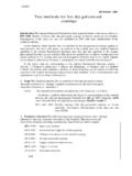
9 Constant individual defined for each grade of pipe for STPG 370 Global Marketing for Tube & pipe for STPG 410 Bendability For the pipe whose nominal diameter is 40A or smaller, In the test of the pipe shall ve free from the occurrence of flaws or cracks on its wall surface, In this case the pipe shall be vent through 90 around an inside radius that is 6 times its outside diameter 6. Hydrostatic Test of Nondestructive Test The pipe shall be tested in accordance with and the resulting hydrostatic characteristic or nondestructive characteristic shall conform to either of the following two.
10 The preference for which of them shall be left to the specification by the purchaser or to the discretion of the manufacturer. Hydrostatic Test When a hydrostatic Pressure specified in Attached Table 1-1 or 1-2 is applied, the pipe shall withstand it without leakage. Nondestructive Test A nondestructive examination by either an ultrasonic test or an eddy current test shall be made on the pipe , and there shall be no signal greater than those produced by the artificial defects of the reference test block of division UD of the working sensitivity specified in JIS G 0582 or of division EY of the working sensitivity specified in JIS G 0583.