Transcription of JIS Universal Joints - Lovejoy, Inc
1 329UJ-JWJISCJSFMCGHPGDDTSPUJVSDRSLDEDJWJ ISCJSFMCGHPGDDTSPUJVSDRSLDEDT able of of ContentsJWJISCJSFMCGHPGDDTSPUJVSDRSLDEDJ WJISCJSFMCGHPGDDTSPUJVSDRSLDEDIn This Section: D Type HD Type D Type Stainless NB (Needle Bearing) Type LOJ Type DD and DDX Type Universal joint BootsUJ-1 Universal JointsJWJISCJSFMCGHPGDDTSPUJVSDRSLDEDJWJ ISCJSFMCGHPGDDTSPUJVSDRSLDEDT able of Contents330630-852-0500 When using Lovejoy products, you must follow these instructions and take the following precautions. Failure to do so may cause the power transmission product to break and parts to be thrown with sufficient force to cause severe injury or to this Lovejoy Catalog for proper selection, sizing, horsepower, torque range, and speed range of power transmission products, including elastomeric elements for couplings. Follow the installation instructions included with the product, and in the individual product catalogs for proper installation of power transmission products.
2 Do not exceed catalog start up and operation of power transmission product, avoid sudden shock loads. Coupling assembly should operate quietly and smoothly. If coupling assembly vibrates or makes beating sound, shut down immediately, and recheck alignment. Shortly after initial operation and periodically thereafter, where applicable, inspect coupling assembly for: alignment, wear of elastomeric element, bolt torques, and flexing elements for signs of fatigue. Do not operate coupling assembly if alignment is improper, or where applicable, if elastomeric element is damaged, or worn to less than 75% of its original not use any of these power transmission products for elevators, man lifts, or other devices that carry people. If the power transmission product fails, the lift device could fall resulting in severe injury or all power transmission products, you must install suitable guards in accordance with OSHA and American Society of Mechanical Engineers Standards.
3 Do not start power transmission product before suitable guards are in place. Failure to properly guard these products may result in severe injury or death from personnel contacting moving parts or from parts being thrown from assembly in the event the power transmission product you have any questions, contact the Lovejoy Engineering Department at WarningTable of ContentsUJ-2 Universal of ContentsUJ-3 Universal JointsOverview ..332 ..UJ-4 Pin & Block > Selection Process ..333 ..UJ-5 Application Service Factors > Selection Data ..334 ..UJ-6D, HD and NB Type Running Curves > Selection Data ..335 ..UJ-7D and HD Type > Dimensional ..UJ-8D 303 Stainless and NB Type > Dimensional Data ..337 ..UJ-9DD and DDX Type > Dimensional ..UJ-10 LOJ and JR-4 Types / Boots > Dimensional Data ..339 ..UJ-11 Running Section Page No. Page of ContentsUJ-4 Universal JointsOverviewLovejoy Pin & Block and Needle Bearing Industrial Universal JointsLovejoy has been manufacturing industrial Universal Joints for over 45 years.
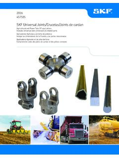
4 Our industrial Universal joint product line is well established and provides you with a wide range of standard and specialized products. The shape of the yoke is a special feature which results in exceptionally high strength, yet allows full, free movement of the joint . This accounts for the high horsepower capacity at high speeds. Features Industry standard Stainless steel and needle bearing available 13 sizes Pin & Block design Boot retaining grooves standardD Type Standard pin and block design Ideal for applications up to 25 of angular misalignment and speeds up to 1,750 RPMHD Type The HD Type Universal joint has induction hardened yoke ears provide longer life than standard D TypeD303 Stainless D Type Universal joint is made from 303 stainless material Ideal for corrosive atmosphere or where sanitation requirements are a factorNB (Needle bearing) Type Designed with high quality, pre-lubricated, and sealed needle bearings Ideal for applications up to 25 of angular misalignment and speeds up to 6,000 RPMLOJ and JR-4 Offset pin design ideal for use on hand operated, low torque drives Capable for operating angles up to 45 of angular misalignmentDD and DDX Types Designed with two Lovejoy D Type Universal Joints and a center connecting shaft DD and DDX Type Universal Joints are tailored to your specific application requirementsUniversal joint Boots The life of a Universal joint can be extended substantially if booted Wear areas of the Universal joint are protected from dirt and contaminants.
5 While lubrication is retained D TypeHD TypeD StainlessNeedle Bearing TypeLOJ TypeUniversal joint BootDD and DDX TypeJWJISCJSFMCGHPGDDTSPUJVSDRSLDEDJWJIS CJSFMCGHPGDDTSPUJVSDRSLDEDWARNINGYou must refer to page UJ-2 (Page 330) for Important Safety Instructions and Precautions for the selection and use of these products. Failure to follow the instructions and precautions can result in severe injury or of JointsPin & BlockSelection ProcessNotes: n * indicates: This is not a recommended operating torque. n 3 indicates: Square and hex bores are measured across the flats. n Operation of all Universal Joints is determined by the angle/speed combinations of the application. Consult Lovejoy Engineering for specific limitations and recommendations. n Applications that fall outside the limitations of these tables should be referred Lovejoy Engineering for assistance. Pin & Block Type Selection ProcessList of Charts provided for Selection: Chart 1 Application Service Factors (page UJ-6) Running Curves (page UJ-7)Steps In Selecting A Universal JointDetermine the correct Universal joint size by working out the following calculations:Step 1: Multiply revolutions per minute (RPM) by working 2: Determine the nominal torque of your application by using the following formulas: in-lbs = HP x 63025 RPMN ominal torque = Nm = KW x 9550 RPMStep 3: Multiply the calculated torque by the desired Application Service Factor from Chart 1 on page 4: Refer to the Running Curves on page UJ-7 that apply to the desired Universal joint .
6 For DD and DDX Universal Joints , use the curve that matches the Universal joint being used. The required Universal joint size can be determined by establishing the point of intersection of the RPM x Working Angle figure on the horizontal scale and the service factor torque of on the vertical scale. Size is stated against the curve immediately above this : n Lubrication is required for optimal wear boots and lubricant extend Universal joint Example A Universal joint is needed to transmit a torque load of 180 in-lbs operating at 1,750 RPM. The working angle required is 5 , and the service factor is 1: RPM x Working Angle = 1,750 x 5 = 8,750 Step 2: Nominal Torque = 180 in-lbsStep 3: Service Factor x Torque = x 180 = 360 Step 4: Find the point of the intersection of 360 in-lbs on the torque scale (vertical) and 8,750 on the RPM x Working Angle scale (horizontal), and the curve immediately above that point will indicate the correct Universal joint size.
7 The proper Universal joint size is D-13 or HD-13 for longer joint Specification ChartUniversalUniversalMaxMax BoreMax Square/MaxStatic Breaking*JointJointAngleNo KeywayHex Hole3 TorqueOffsetRoundTypeSizeinmminmmRPMin-l bsNmD-TypeD-1 to D-1425 ,75065,4007 389HD-TypeD-1 to D-1425 ,75065,4007 389D StainlessD4, 6, 8, 10, 1225 ,75010,4001 175 Needle BearingD6, 8, 10, 1225 ,00010,5001 186 LOJLOJ6, 8, 1045 See Data See Data 3,480393 LOJ JR-4JR-445 See Data See Data 18020 Multi-spindleD-1 to D-1425 ,75065,4007 389 JWJISCJSFMCGHPGDDTSPUJVSDRSLDEDJWJISCJSF MCGHPGDDTSPUJVSDRSLDED334630-852-0500 Table of ContentsUJ-6 Universal JointsApplication Service FactorsSelection DataApplication Service FactorsChart 1 Agitators Pure Liquids .. Liquids Variable .. Puller .. Centrifugal .. Lobe .. Vane .. Filling Machinery .. Dumpers .. Pullers .. Centrifugal.
8 Lobe .. Reciprocating ..not recommendedConveyors, Uniformly loaded or fed Assembly .. Belt .. Screw .. Bucket .. Live roll, shaker, and reciprocating .. (Heavy Duty), Not uniformly fed Assembly .. Belt .. Reciprocating .. Screw .. Shaker .. & Hoists1 Main Hoists .. Reversing .. Skip .. Trolley Drive .. Bridge Drive .. Slope .. Ore .. Stone .. Cable Reels .. Conveyors .. Cutter Head Drives .. Maneuvering Winches .. Pumps .. Consult Factory .. Centrifugal .. Cooling Forced Draft .. Induced Draft w/o Damper Control .. Propellor .. Induced Draft w/Damper Control .. Belt .. Screw .. Reciprocating .. Not Welding .. Welding .. Hoist .. Mills .. Washers Reversing .. Shafting Any Processing Mach .. Machinery Barkers .. Edger Feed.
9 Live Planer .. Slab Conveyor .. Tools Bending Roll .. Plate Planer .. Punch Press Gear Driven .. Tapping Machinery .. Other Main Aux. Drives .. Forming Machines Draw Bench Carriage .. Draw Bench Main Drive .. Extruder .. Forming Machinery .. Slitters .. Table Conveyors Non-reversing .. Reversing .. Wire Drawing .. Wire Winding .. Coilers .. , Rotary Type Ball .. Cement Kilns .. Dryers, Coolers .. Kilns .. Pebble .. Rolling .. Tube .. Tumbling .. Concrete, Continous .. Muller .. Mills Agitators (Mixers) .. Barker, Mechanical .. Barking Drum Spur Gear .. Beater & Pulper .. Calenders .. Converting Machines .. Conveyors .. Dresses .. Jordans .. Log Haul .. Reel .. Super Calenders .. Winder .. Presses .. Mill .. Centrifugal.
10 Gear, Rotary, or Vane .. Reciprocating 1 cyl. single or double acting .. 2 cyl. single acting .. 2 cyl. double acting .. 3 or more cyl.. Machinery Mixer .. Rubber Calender .. Air Washing .. Rotary Stone or Gravel .. Vibrating .. Water .. Grizzly .. Gear ..not recommendedStokers .. Machinery Dyeing Mach.. Tumbling Barrel .. Windlass .. Woodworking Machinery .. Notes: n 1 indicates: If people are transported, Lovejoy does not recommend and will not warranty the use of the coupling. n The values contained in the table should be used as a general guide. n For above average shock loads or start/stop conditions of not more than once per hour, add .5 to the table value. n Universal Joints are not recommended for internal combustion engine applications. n For severe shock loads or reversing loads, or start/stop conditions of more than once per hour, add 1 to the table of JointsD, HD and NB Type Running CurvesSelection DataRunning CurvesD and HD TypeWorking Torque in-lbsWorking Torque in-lbsRPM x AngleRPM x AngleNB TypeJWJISCJSFMCGHPGDDTSPUJVSDRSLDEDJWJIS CJSFMCGHPGDDTSPUJVSDRSLDED336630-852-050 0 Table of ContentsUJ-8D and HD Type Dimensional DataOALECID1 - ID2 ODMain PinBoreStdMax BoreMax BoreMax Square/Static*WeightSizeHeight DepthBoreNo Keywaywith KeywayHex Hole3 Breaking.