Transcription of Joints in Concrete Buildings - ccaa.com.au
1 Any joint , as in a physical break or gap betweenmembers, in a Concrete structure or building is apotential weak link which may lead to serviceabilityproblems, lack of durability or structural failure. Yetseldom, if ever, is a building constructed withoutthem. In many situations they are necessaryrequirement (eg to accommodate anticipateddifferential movement between members) and aresometimes regarded as a necessary evil. Frequently,problems arise because they are given insufficientattention by designers both in terms of theirlocation and detail Technical Note reminds designers of thereasons for including Joints in Buildings and theperformance requirements they should meet. Itgives some guidance on their planning, design anddetailing and provides examples of Joints whichhave performed in Concrete BuildingsTECHNICAL noteJoints in concretebuildingsPanel-to-panel Joints and false Joints articulatethe cream GRC cladding and the reconstitutedgranite podium cladding at St George PrivateMedical Complex Kogarah NSWDEFINITIONThe word joint is used in building parlance to coverelements which have to perform quite differentfunctions, eg beam -column Joints and isolationjoints.
2 In the former the joint has to provide continuityof structural action between the members meetingat the joint . In the latter the joint has to ensureseparation between the adjacent members to allowone member to move independently of the Technical Note deals primarily withisolation Joints and tends to use Joints in this , a discussion of construction Joints isincluded because they are frequently referred to ininsitu Concrete are a number of ways in which Joints canbe classified apart from the broad division statedabove. In this Technical Note a limited number ofspecific Joints defined by their situation Joints ARE NEEDEDThe four basic reasons for requiring Joints arebecause the member or structure cannot be constructedas a monolithic unit in one placement ofconcrete; the member has to be of limited size so it canbe handled by cranes, etc; the structure or member on one side of the jointneeds to be able to move relative to that on theother; the design assumptions for the structure orbuilding need the joint at that point so theanalysis is is a major difference in the objectives andrequirements for Joints constructed for the firstreason (construction Joints ) compared to the third(isolation Joints ) as already noted.
3 This TechnicalNote does not address Joints required for JOINTSA construction joint is defined by the ACI1as thesurface where two successive placements ofconcrete meet, across which it may be desirable toachieve bond and through which reinforcement maybe continuous . Generally, because continuity ofstructural action will be required across the joint ,bond will be desirable and the reinforcement will Joints may be either planned construction Joints The location anddetailing of planned construction Joints can beconsidered and prepared. The location should bedetermined in conjunction with the contractor. Thecontractor will be able to define the maximum sizeof Concrete placement possible on the particularproject taking into account the anticipated rate ofplacement and the constraints imposed by finishingrequirements. Where possible, the day s placementshould terminate to coincide with other Joints in Joints should be on a single planeand preferably located at right angles to the mainreinforcement.
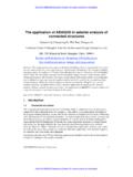
4 They should preferably be vertical orhorizontal to the member. Keys are sometimesincluded but these can lead to difficulties instripping. If possible, they should be positionedaway from regions of high shear or high 36002requires that in columns and walls aconstruction joint be formed logically at the soffit ofthe beams and slabs they support Figure 1. Duringplacement the Concrete adjacent to the joint shouldbe well compacted and special attention should bepaid to vibration. The joint should be stripped whenthe Concrete has set and hosed down to expose thecoarse aggregate. Any problems in stripping of thejoint will be eased if it is located away from regionsof high moment and reinforcement prior to placing Concrete in the nextsection, the surface should be coated with a details for a construction joint in aconcrete pavement or industrial floor on grade areshown in Figure 2.
5 The slab reinforcement iscarried through the joint and extra tie bars areinserted to hold the two sides 2 Joints in Concrete BuildingsTop of floorBeam soffitScabble and cleanlaitence off surfaceprior to placingbeam reinforcementLongitudinal columnreinforcementFigure 1 Stop-board to form jointDFigure 2 Unplanned construction Joints These are jointsthat are forced upon the Concrete -placing crewbecause of an interruption in supply of a durationlong enough for the Concrete to take its initial is no opportunity to plan their to follow can be only indicated. As withplanned Joints , the Concrete should be cut back tobroadly approximately a single plane and the facemade vertical. Top ends should be used wherepossible and the Concrete vibrated against forming and clearing the excess concreteaway, the joint should be treated as for plannedconstruction REQUIREMENTSD esigners and specifiers of Joints should have aclear understanding of the specific requirements forany joint on a specific project.
6 These will range fromweathertightness to ease of maintenance and repair,and will be discussed under each specific joint , there are a few aspects which warrantdiscussion before looking at the specific joint types: Buildability and minimum sizeDesignersshould be confident that the chosen detail canbe easily fabricated and will permit easy andsafe construction. Proven details should bereused where appropriate; reinvention of thewheel should be avoided. Joints must be wideenough to accommodate the tolerances offabrication, construction and erection. Thisusually means a minimum width of 20 mm. Maintenance and repairAs noted earlier, jointsare the focal point for wear and deterioration;aspects of maintenance and repair should beconsidered at the design stage. The choice of asuitable sealant is important as is the appropriatesealant cross-section. Although today s sealantsare long-lasting, they eventually will needreplacement or repair; the process and ease ofthis should be part-and-parcel of joint should be provision for inspection andmaintenance of face sealants.
7 Locatingdownpipes in front of a face-sealed joint , whilstprotecting the sealant from UV light, impedesboth inspection and repair. SealantsThese are proprietary products and theadvice on particular products should be obtainedfrom the particular manufacturer/supplier, eg on cross-section dimensions for the sealantand precautions to be taken during , the ACI Guide to Sealing Joints inConcrete Structures3provides sound adviceregarding the various types of sealant, how theyfunction, joint details, installation andperformance, repair and suggests that the required properties of a jointsealant are that it: be impermeable material; deform to accommodate the movement and rateof movement occurring at the joint ; sufficiently retain its original properties andshape if subjected to cyclical deformations; adhere to general, field-moulded sealants suitable forface sealing Joints between precast wall claddingpanels will be either polysulphides, polyurethanesor minimise the strain on the sealant as thejoint opens or closes, a rectangular cross sectionwith a larger width than depth across the joint ispreferred.
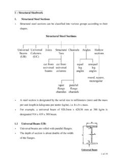
8 The use of backup materials to controlthe depth of sealant is therefore STRUCTURE ISOLATIONJOINTD escriptionA joint occurring where a pavement,(ground-supported floor) abutts a structure; itallows the pavement and adjacent structure tomove relative to each other Figure joint should not impede anyrelative movement. This may be horizontal, verticalor both and may include rotation. Concrete dryingshrinkage in the pavement will mean the joint willusually open with time. However, temperaturechanges and prestressing forces may give rise tojoint closing movements. The Joints should besealed to prevent ingress of detritus which mayinhibit this movement. Ability to resist positive waterpressure is not usually required; if it is required,reference should be made to Joints for water-retaining filler material and sealant shouldbe capable of accepting the required expansion andoffer little resistance to any compression.
9 The facesshould be well compacted during construction togive a smooth finish which offers little resistance tovertical determined by the location of theadjacent structure. Where possible, other jointsshould be aligned in the same plane Figure 5. Avoidthe creation of re-entrant angles in the floor panelsas these function as crack 3 Joints in Concrete BuildingsSealantAbutting structureFillerFigure 3 GROUND-SUPPORTED FLOOR FLOORCONTRACTION JOINTD escriptionA joint between one section of aground-supported floor or pavement and theadjacent section to allow the shrinkage of theconcrete to occur at defined joint should allow theshrinkage of the adjacent sections to take placeacross the joint , preferably at right angles to theplane of the joint . Any relative vertical displacementacross the joint should be prevented. Althoughmovement will open the joint , it should neverthelessbe sealed to prevent ingress of detritus which couldinhibit any partial closing of the joint due totemperature to resist positive water pressure is notusually Joints are usually constructed bysawing a groove to at least a quarter of the depth ofthe slab.
10 Reinforcement should be terminated atleast 50 mm, preferably 75 mm, from the jointlocation. Dowels should be placed through the jointparallel to the direction of shrinkage, ie perpendicular to the plane of the joint Figure timing of the saw cuts is critical andgenerally will be between 6 24 hours after the cut is made too early the edges of groove willravel; if too late, the slab will randomly crack,defeating the object of the joint . The advice ofspecialist saw-cutting contractors should beobtained for each project as the timing for sawcutting is affected by Concrete mix design, ambienttemperatures, and Concrete placing control joint details can be found plan shape of the particularpavement will have a marked influence on the jointlayout and location as will the anticipatedconstruction technique. Generally, for reinforcedfloor slabs strip placement is preferred; the width ofthe strip is limited by the span of the beamvibrators to be used.